Chapter 5. Solid-State NMR Accessories
73
VNMR 6.1C User Guide: Solid-State NMR 01-999162-00 C0402
• The time between successive edges can be measured (note that the edges are always in
the same sense, so that this interval is one rotor period). This has a precision of 50 ns.
This is shown as “mode 1" in Figure 27.
• An event can be triggered on the nth edge (in all cases here n is an integer). In this
mode, the rotor is providing an external timing event to the Acquisition Controller or
Pulse Sequence Controller board. This provides a means of delaying until the next
dark-to-light rotor edge. This is “mode 2" in Figure 27.
• The Acquisition Controller board or Pulse Sequence Controller board can be instructed
to delay precisely n rotor periods. This is done by interrupting an internal counter that
is normally reset at each rotor edge, delaying n edges and then counting the counter
down to zero. At this point the delay is finished. Thus, in principle, the error in the
delay will be only that percentage that the first and the last periods differ. This is shown
as “mode 3" in Figure 27.
A potential source of error exists in determining the point of the light transition on which
to trigger the digital circuitry. This is a factor determined by two variables: the light
detection circuitry and the markings on the rotor.
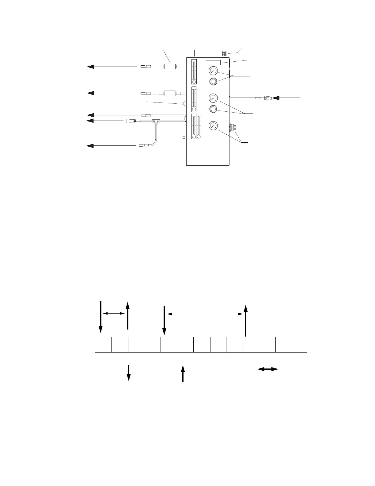
Figure 26. Pneumatics/Tachometer Box for CP/MAS Probes
Flow meter/valveFilter
Bearing to probe
Rotation/drive to probe
Rotation trigger adjust
Body N2 to probe
To eject port
of magnet
Angle adjust tool
Purge to heat exchanger
Tachometer counter
N2 supply in
Bearing pressure
regulator and gauge
Body pressure
regulator and gauge
Drive pressure
regulator and gauge
Figure 27. Different Modes of the Rotor Synchronization Accessory
Delay 5 periods
(mode 3)(mode 2)
= start of event = end of event
Rotor period
(mode 1)
Trigger on
2nd edge