Series 642 INSTALLATION
813316EB Edition 2017-11-24 19/
4.3 Tightening torque
Tighten mounting screws of the flanges uniformly in crosswise order. Observe the maximum torque
levels in the following tables.
4.3.1 Mounting with centering rings
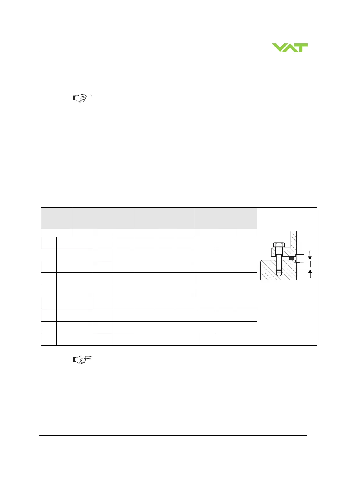
DN
max. torque
(Nm)
max. torque
(lbs . ft)
Max. hole depth [d]
(mm)
mm inch ISO-F JIS ASA-LP
ISO-F JIS ASA-LP
ISO-F JIS ASA-LP
63 2 1/2 8 – 10 8 – 10 8 – 10 6 – 8 6 – 8 6 – 8 13 13 15
80 3 8 – 10 8 – 10 8 – 10 6 – 8 6 – 8 6 – 8 13 13 15
100 4 8 – 10 8 – 10 8 – 10 6 – 8 6 – 8 6 – 8 13 13 15
160 6 13 – 15 13 – 15 20 - 30 9 - 11 9 - 11 15 – 22 14 14 15
200 8 13 – 15 13 – 15 20 - 30 9 - 11 9 - 11 15 – 22 16 16 20
250 10 17 – 20 17 – 20 40 – 60 13 – 15 13–15 30 – 44 16 16 20
320 12 17 - 20 17 – 20 40 - 60 13 – 15 13–15 30 - 44 16 16 20
350 12 17 - 20 17 – 20 40 - 60 13 – 15 13–15 30 - 44 16 16 20
400 16 17 – 20 30 – 35 55 – 80 13 – 15 22 – 26 41 – 59 25 25 NA
The torque values below are dependent on many factors, such as materials involved,
surface quality, surface treatment, and lubrication.
The torques below are valid if immersion depth of the mounting screws is at least
once the thread diameter (min. 1d), and the friction coefficient of the screw-flange
connection (µ
total
= (µ
screw thread-helicoil
+ µ
under screw head
)/2) is bigger than 0.12. Lower
friction coefficients may damage the valve, as the resulting preload force gets too
high. Therefore for other friction coefficients the torque needs to be adapted. Please
review design guidelines for Helicoil-Screw connections and make sure that screws in
use are capable to withstand applied torques, are appropriate for the application and
are not too long. Too long screws may damage the valve, the immersion depth should
Refer to «Spare parts / Accessories» for centering rings ordering numbers.
 Loading...


