Series 642 INSTALLATION
813316EB Edition 2017-11-24 63/
4.9 CC-Link interface (Process data – cyclic communication)
The buffer naming is in view from customer (master) PLC.
Data format: All signals are transmitted and received in intel format (low byte first).
All one-byte signals use the least significant byte (LSB).
Neither valve display information nor CONTROL MODE values or any other fieldbus
cyclic/acyclic data are related to any fieldbus states/notation
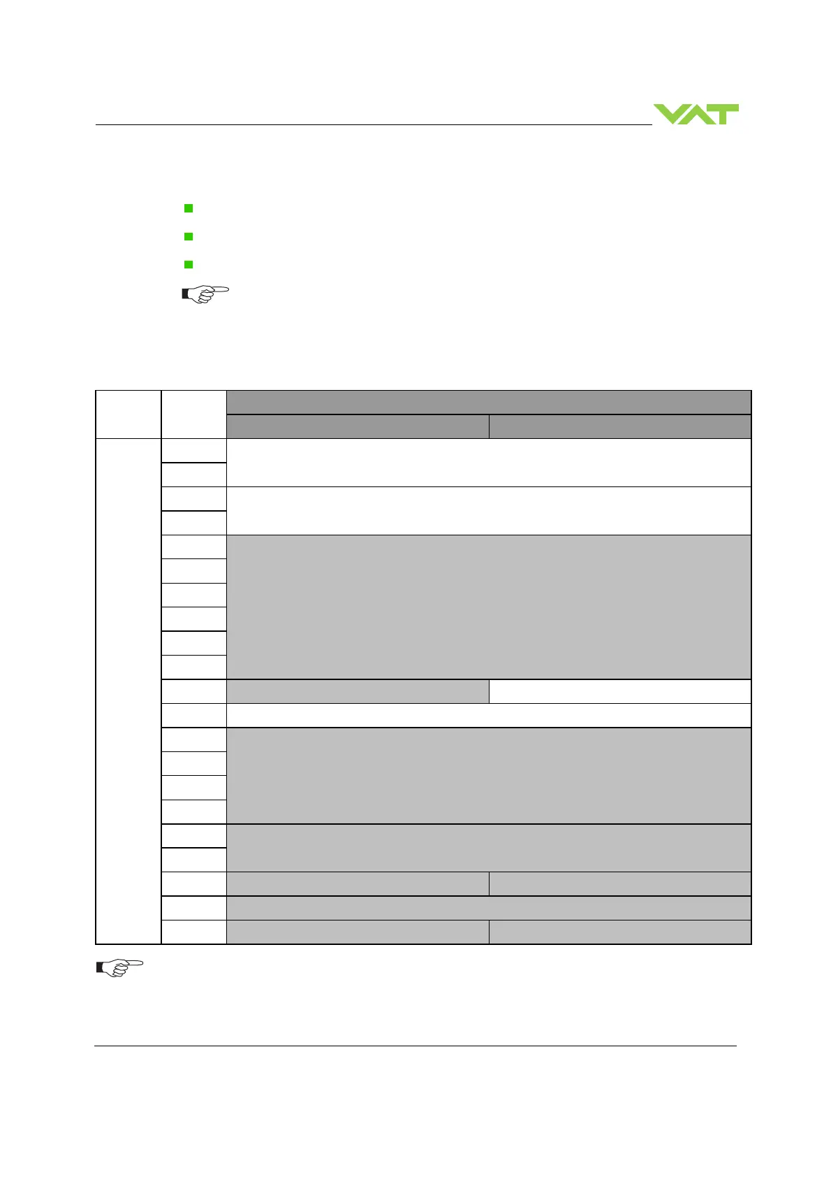
4.9.1 OUTPUT Buffer (Master PLC)
4.9.1.1 Overview
Data
model
Index
Buffer
Contents (MSB) Contents (LSB)
16 bit
(Word)
0
Pressure setpoint
1
2
Position setpoint
3
4
Not used – reserved
5
6
7
8
9
10
Not used – reserved
Control mode setpoint
11 General control setpoint
12
Not used – reserved
13
14
15
16
Not used – reserved
17
18
Not used – reserved Not used – reserved
19
Not used – reserved
20
Not used – reserved Not used – reserved
For data consistency make sure your master PLC is supporting “block guarantee of cyclic data per station”.
 Loading...


