Series 642 INSTALLATION
813316EB Edition 2017-11-24 61/
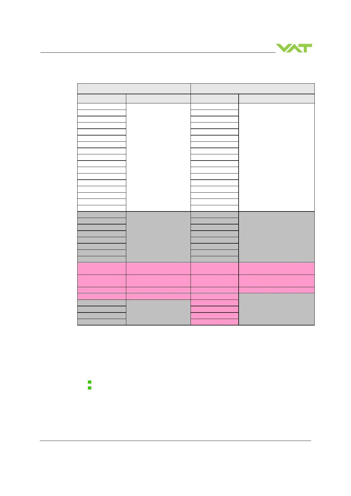
4.8.2 Location of the handshaking bits
Slave
Master Master
Slave
Device Signal name Device No. Signal name
RX m0
Not used
RY m0
Not used
RX m2 RY m2
RX m4 RY m4
RX m6 RY m6
RX m7 RY m7
RX m8 RY m8
RX m9 RY m9
RX mB RY mB
RX mD RY mD
RX mF RY mF
RX(m+n)0
Reserved
RY(m+n)0
Reserved
RX(m+n)2 RY(m+n)2
RX(m+n)4 RY(m+n)4
RX(m+n)5 RY(m+n)5
RX(m+n)6 RY(m+n)6
RX(m+n)7 RY(m+n)7
RX(m+n)8 Initial data processing
request flag
RY(m+n)8 Initial data processing
complete flag
RX(m+n)9 Initial data setting
complete flag
RY(m+n)9 Initial data setting request flag
RX(m+n)A Error status flag RY(m+n)A Error reset request flag
Reserved
RX(m+n)C
Reserved
RY(m+n)C
RX(m+n)E RY(m+n)E
Table 1: Bit Memory Map Profile of VAT CC-Link slave
m: Address assigned to the master module by the station number setting. This means that the address
range for this slave begins at address m of the master.
n: Dependent on the VAT Operational settings mode (number of occupied stations and number of
extension cycles)
Operational settings mode = 1 n = 0x7 (hex)
Operational settings mode = 4 n = 0xD (hex)
Example see chapter: 4.8.3 Example of the handshaking by a PLC-program.
 Loading...


