Series 642 INSTALLATION
813316EB Edition 2017-11-24 37/
4.6 Initial operation
4.6.1 Setup procedure
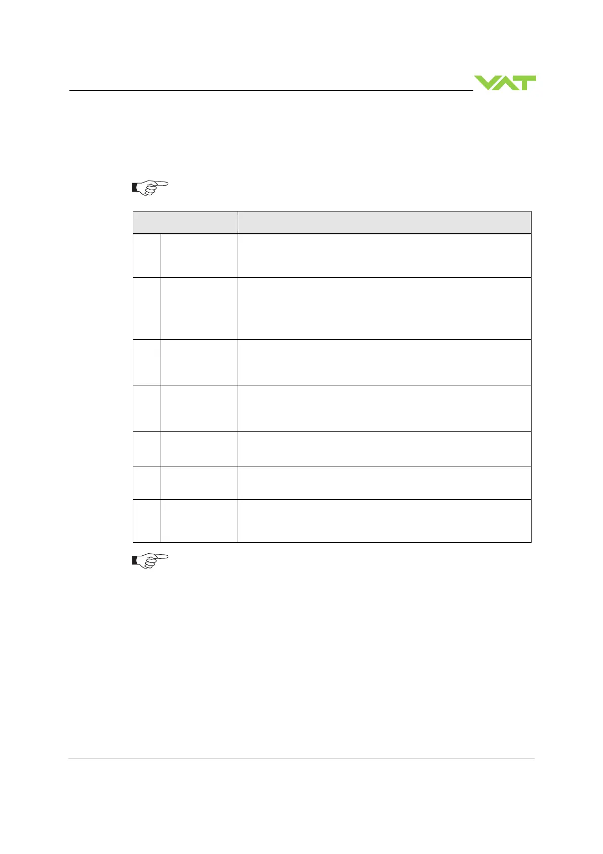
To enable the valve for
setup steps
.
In case position control is required only it’s sufficient to perform steps 1 to 5.
Setup step Description
1
Power up
Turn on external + 24VDC power supply (and external ±15 VDC for
sensor power supply if required). Refer to chapter «Behavior during
power up» for details.
2
CC-Link
configuration
1. Station Number
2. Transmission rate
3. Operational settings mode
Refer to chapter «CC-Link configuration» for details.
3
Valve
configuration
Basic configurations of the valve must be adapted according to
application needs.
Refer to chapter «Valve configuration» for details.
4
Sensor
configuration
Basic configurations of the valve must be adapted according to
application needs.
Refer to chapter «Sensor configuration» for details.
5
ZERO
Compensation of the sensor offset voltage.
Refer to chapter «ZERO» for details.
6a
LEARN
Determination of the vacuum system characteristic to accommodate the
PID controller. Refer to chapter «LEARN adaptive» for details.
6b
PRESSURE
CONTROL
COFIGURATION
Accommodation of PID controller to the vacuum system characteristic.
Refer to chapter: «Pressure Control configuration» for details.
Without «LEARN adaptive» or «Pressure Control configuration» the valve is not
able to run pressure control.
•
For ease setup (in Local mode) of ‘Interface’, ‘Valve’, ‘Sensor’, ‘Senor ZERO’,
‘LEARN’ and ‘PRESSURE CONTROL COFIGURATION’ it is possible to use the
CPA 3.0, The free download is available on the VAT homepage:
http://www.vatvalve.com/customer-service/informations-and-downloads/control-
performance-analyzer
 Loading...


