INSTALLATION Series
26/107
Edition 2017-11-24 813316EB
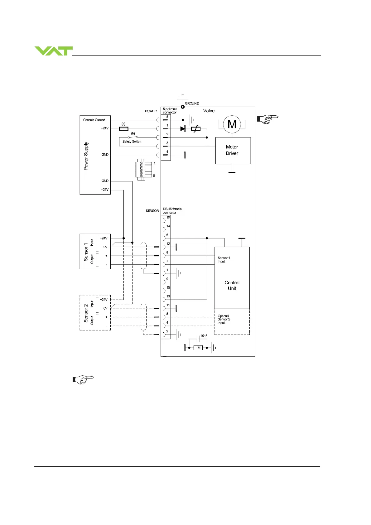
4.5.3.2 +24 VDC power to supply +24 VDC sensors externally
•
VAT fuse recommendation: (a) 5AF, / (b) Safety switch min. 3A
•
Use shielded sensor cable(s). Keep cable as short as possible, but locate it away
from noise sources.
•
Connect Power supply (+24 / GND) at power 5 pol. male connector and Sensors
(0V / + / -) at DB–15 female sensor connector exactly as shown in the drawing
above!
Pins 2 and 3 must be
bridged for operation.
An optional switch
would allow for motor
interlock to prevent
valve from moving.
SC1 091 A
 Loading...


