Console Touch Screen Overview TLS4 Comm Ports - Menu>Setup>Communication
4
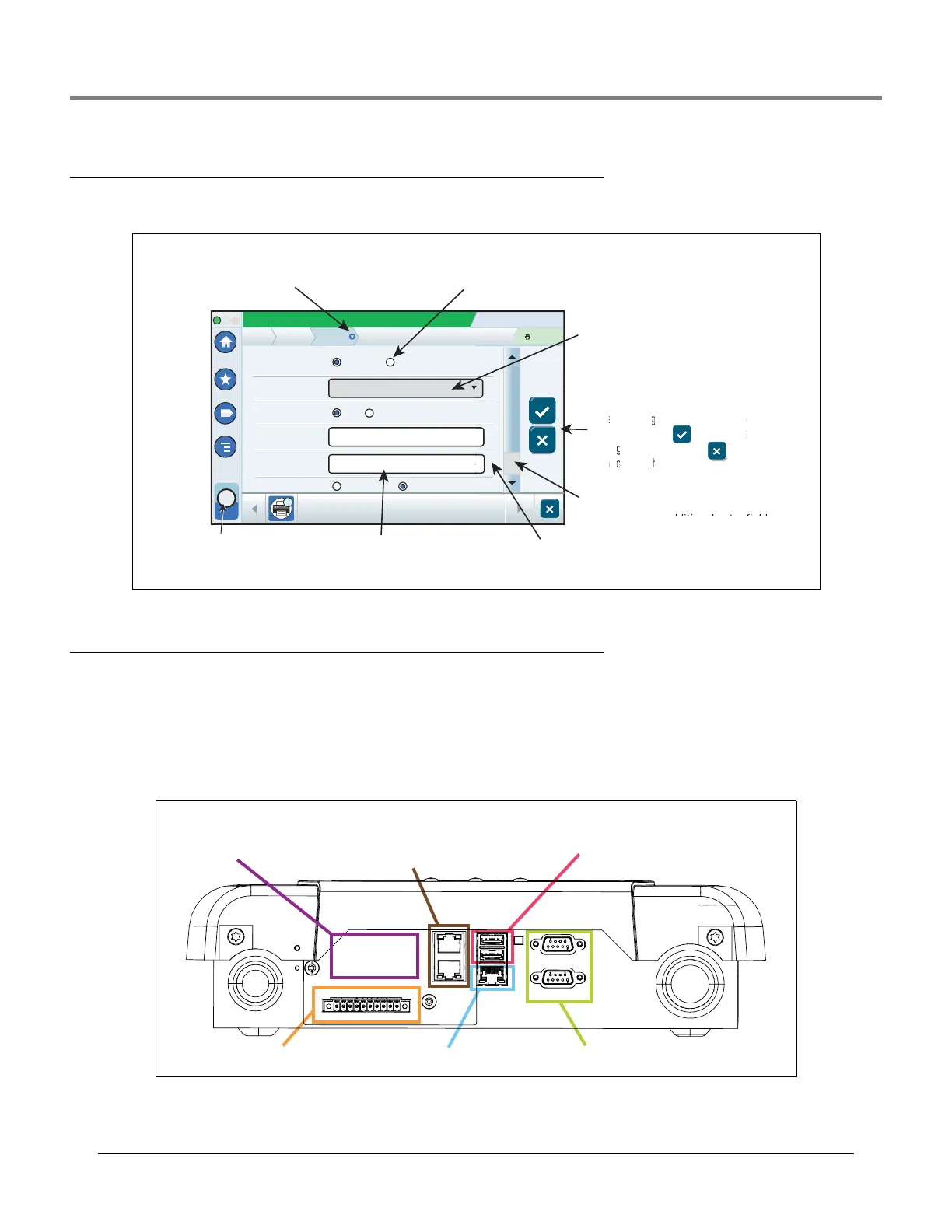
Entering Changes On A Touch Screen
The screen example below describes entering data into the screen’s field windows.
Console Comm Ports
When setting up comm ports, you should verify the connections to the console’s comm ports prior to entering their setup
parameters.
TLS4 Comm Ports - Menu>Setup>Communication
Your console’s Comm Port configuration will depend on features ordered. Note: Ethernet ports 2 and 3 are programmed as
the same ethernet device.
Figure 1. TLS4 Comm Ports
After making any change to a screen
entry, touch the key to accept the
change(s) or touch the key to
cancel the change(s).
System Status
07/20/2013 09:01 AM
Printers
0 Warning(s)
0 Alarms(s)
Print (0)
Home
Favorites
Menu
Actions
Setup
Configured
Driver Selection
Printer
Is Default
Label
URI
1
APS_CP324HRS_640_USB_1
TLSIntegralPrinter
dev/bus/usb?type=usb+vid=6868+pld=4
Yes No
Enabled Disabled
Automatic Manual
Setup
1
Printer
ca
4
Aft
ent
ch
A grayed-in field cannot be changed.
In this example, if there two or more
printers, the field would be white and
touching the down arrow would display
the additional printers.
Touching in a white field displays
a pop-up keyboard/keypad to enter
or modify an entry.
Selected device. Touch to select
additional devices to be programmed,
in this case additional printers.
If page scroll is visible, touch the up/down
arrows or slide bar with finger to scroll up
or down to view additional entry fields.
An asterisk (*) next to a field indicates you
changed
an entry for that field before you have accepted or
saved the change in a dialog window.
White (empty) radio button indicates item is not selected.
Touch radio button to select Disabled and deselect Enabled.
Touch down arrow in a menu
breadcrumb to view all additional setup
s
creens, select any in list to jump
to that screen
.
scroll
makin
touc
(s) o
l the c
i
e bar with finger to scroll
creen
pt t
e
to
up/d
s visible, touch th
ange
s
.
*
USB port (1) upper
USB port (2) lower
SWITCH ETH 2 & 3 - shown
in Setup menu as
Ethernet Port 2 (Optional)
Factory Installed,
Optional Module
Area
VR Bus port Ethernet port (1) RS-232 or RS-485 DB9 ports
EXPANSION
SERIAL 1
SERIAL 2
ETH 2
ETH 3
USB 1
USB 2
ETH 1
 Loading...