Initial Setup Of The Console Using Workflow Wizard Setup>Pumps and Lines>PLLD
42
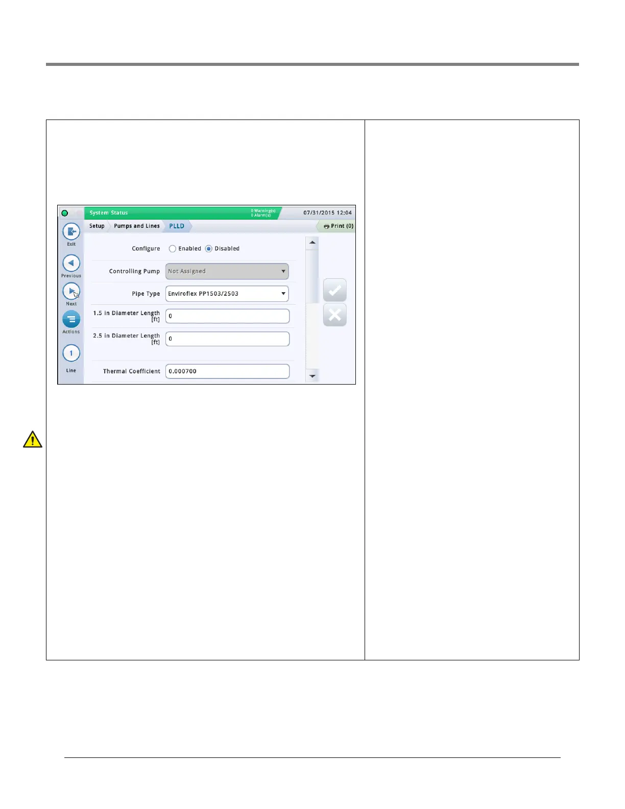
Setup>Pumps and Lines>PLLD
This screen lets you setup parameters for individual lines when Pressurized Line Leak Detec-
tion (PLLD) is enabled. Also, if Leak Monitoring is not enabled (in “Setup>Pumps and
Lines>Line”) for at least one line, then none of the PLLD screens can be edited.
The maximum number of lines that can be configured for Leak Detection is equal to the max-
imum number of STPs as determined by your console. However, only those lines for which
Leak Monitoring is enabled (in “Setup>Pumps and Lines>Line”) are shown.
Automatic dialing or sending of PLLD alarms is setup in Automatic Events setup (Setup>
Automatic Events).
Select a line from the icon list on the bottom of the screen to configure.
Configured
Touch the radio button to enable or disable the PLLD feature for the selected line.
NOTE: In setup wizard, you should enable settings as you go.
Controlling Pump
Touch to enter pump controlling this tank. Note: Pump must be programmed to use Pump
Control (see “Setup>Pumps and Lines>PLLD” on page 42).
Pipe Type
Touch to enter the pipe type for this line. Refer to the ‘Supported Pipe Types and Line Lengths’
table in the Veeder-Root Electronic Line Leak Detectors Application Guide (P/N 577013-465).
NOTE: The fields that display below are dependent on, and applicable to, the Pipe Type
selected. For example, if you select 2/3 IN. FIBERGLASS, the applicable fields that display
will allow you to enter lengths for the 2" diameter and the 3" diameter pipe. If you select
"user defined" pipe type, fields for setting up the 1st and 2nd line diameters, line lengths,
and bulk modulus will display.
Line Length
The length of the piping between the tank and the dispensers, including the length between
the check valve and where it connects into the product line. Line lengths are whole numbers.
Values are in foot or meter increments, depending on system units.
Allowable selections:
Refer to the ‘Supported Pipe Types and Line Lengths’ table in the
Veeder-Root Electronic Line Leak Detectors Application Guide (P/N 577013-465).
The default is 0 but leaving it at 0 after entering a line length will cause a data setup warn-
ing.
Line Diameter
Allowable selections: 0 to 3.00 in (0 to 76.20mm)
The default is 0 but leaving it at 0 after entering a line length
will cause a data setup warning.
2nd Line Length
Allowable selections: Refer to the ‘Supported Pipe Types and
Line Lengths’ table in the Veeder-Root Electronic Line Leak
Detectors Application Guide (P/N 577013-465).
Default: 0
2nd Line Diameter
Allowable selections: 0 to 3.00 in (0 to 76.20mm)
The default is 0 but leaving it at 0 after entering a line length
will cause a data setup warning.
1st Line Bulk Modulus
[only available if the pipe type is user-defined]
The line's resistance to uniform compression.
Refer to the ‘Supported Pipe Types and Line Lengths’ table in
the Veeder-Root Electronic Line Leak Detectors Application
Guide (P/N 577013-465).
Allowable selections: 1000 to 200,000 psi (6892 to
1,378,359kPa).
The default is 0 but leaving it at 0 after entering a line length
will cause a data setup warning.
2nd Line Bulk Modulus
[only available if the pipe type is user-defined]
The line's resistance to uniform compression.
Refer to the ‘Supported Pipe Types and Line Lengths’ table in
the Veeder-Root Electronic Line Leak Detectors Application
Guide (P/N 577013-465).
Allowable selections: 1000 to 200,000 psi (6892 to
1,378,359kPa)
The default is 0 but leaving it at 0 after entering a line length
will cause a data setup warning.
Thermal Coefficient
If the controlling pump assigned to the line has a tank
assignment, this field is set to the thermal coefficient from
that tank (see “Setup>Tank>General”) and the field is
read-only. If there is no tank assignment, you can edit this
field. If the tank assignment is removed, the system will use
the default thermal coefficient 0.00070 U.S. Units (0.00126
Metric Units).
Allowable selections: 0.0 to 0.0016 gal./gal./°F (0.0 to
0.00288 lit./lit./°C)
 Loading...