OTDR Series e-Manual, D07-00-076P-RevC00 Page 55 of 107
6.9.1 Using the VFL
To operate the VFL:
1. Make sure laser is turned off. Remove connector covers from the cable.
2. Connect the fiber to the VFL port located at the top of the unit. The VFL interface is fitted
with universal 2.5mm sleeve accepting all 2.5 mm connector ferrules.
3. Use Test App 1 – Test Mode Selection Fiber testing to display the VFL App.
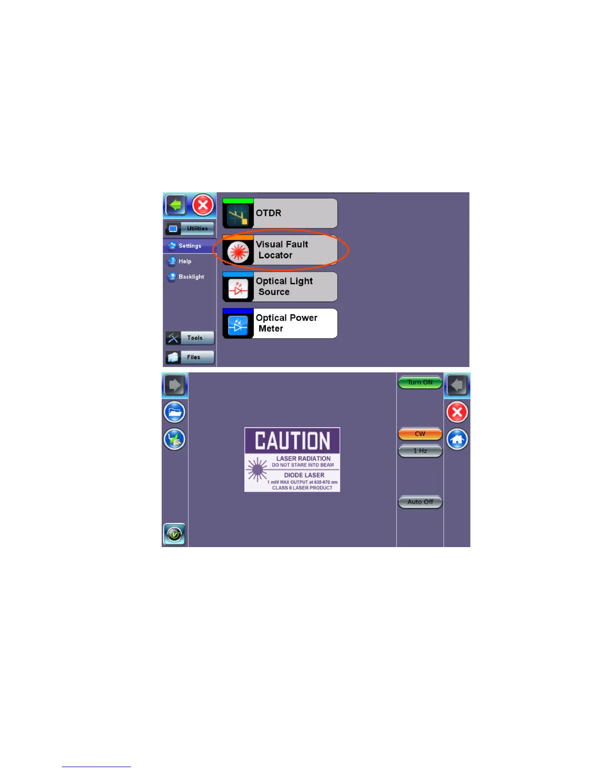
4. Press Visual Fault Locator on the main menu. The Caution screen appears.
5. Select the operation mode.
CW: Continuous Wave. Select this option to turn on the VFL continually to check for
faults.
1 Hz: Pulse. Select this option to send intermittent light pulses. In some cases, this
makes it easier to identify faults (than continuous light). It can also be used with audible
detectors (toners) that can identify faint light or in well-lit (bright) environments.
6. Press Auto Off. When VFL application is exited, the VFL powers down automatically.
7. Press Turn ON to power the laser. The Caution box turns yellow.
8. You will observe that a red light emits from the end of the fiber to confirm continuity. This
red light will also appear at splices, joints, connectors, ODLs, etc. if any light is leaking.