20000028
Page :1 /1
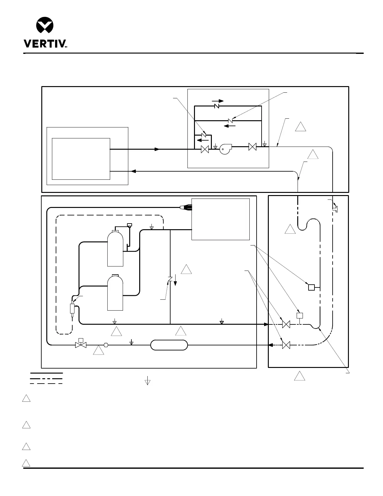
DA250 & DA265 W/ LIEBERT® MCV WITHOUT RECEIVERS
Form No.: DPN001040_REV4
PIPING SCHEMATIC WITH OPTIONAL OIL SEPARATOR
LIEBERT® DSE
REV: B
REV DATE: 02/2024
Electronic
Expansion
Valve
LIQUID
EVAPORATOR
COIL
SUCTION
Trap at base of risers
over 5ft. (1.5m)*
LIQUID RETURN
HOT GAS DISCHARGE
For rises over
25ft. (7.6m), trap
every 20ft. (6m)
or evenly divided*
Ball Valve
Ball Valve
Check
Valve
Notes:
1. Two refrigeration circuits provided. Single refrigeration circuit shown for clarity.
2. Circuit 1 must be maintained between indoor unit, condenser and Liebert® EconoPhase unit. Circuit 2 must be maintained between indoor unit, condenser and Liebert® EconoPhase unit.
3. Schematic representation shown. Do not use for specific connection locations.
4. The bottom of the condenser coil must be no greater than 60 ft (18.3m) above and less than 15 ft (4.6m) below the elevation of the EEV inside the indoor unit.
5. All indoor field refrigerant piping must be insulated, 1/2" minimum thickness. All outdoor field refrigeration piping does not need to be insulated.The installing contractor is responsible
for the insulating, securing, protecting and the proper installation of all field refrigerant piping, observing the details outlined by the Engineer of Record.
6. Components are not supplied by Liebert but are required for proper circuit operation and maintenance (DA250 and DA265 with top piping has internally installed traps on the
discharge lines).
7. Traps must be installed and horizontal lines pitched to ensure proper oil return and to reduce liquid flood back to compressor. Pitch horizontal gas piping at a minimum of
1/2" per 10 feet (42mm per 10m) so that gravity will aid in moving oil in the direction of the refrigeration flow.
8. Vertiv requires installing external refrigerate isolation valves on the Liquid line entering and Hot Gas line leaving the indoor unit . The external isolation valves are required to allow
service to safely evacuate the refrigerate charge from the indoor unit before serving the compressors, filter drier, or other refrigeration components. Prior to closing isolation valve
on Liquid Line, put indoor unit into evacuation mode, which will open EEV to allow migration of liquid refrigeration from this piping.
9. Typical location for Sight Glass on DA125, DA250, and DA265. On DA150 and DA165, Sight Glass is located between Filter Drier and customer piping connection.
Check Valve
included only
on Liebert®
EconoPhase
ready models.
Liquid to Indoor Unit
Differential
Check Valve
Differential
Check Valve
SERVICE/SCHRADER (ACCESS) CONNECTION, WITH VALVE CORE.
FIELD PIPING
FACTORY REFRIGERANT PIPING
2
2
6
6
Filter Drier
2
2
INTERCONNECTING PIPING
Hot Gas
Discharge
from Indoor
Unit
Liebert
®
MCV HEAT REJECTION SKID
Optional Liebert
®
EconoPhase UNIT
Liebert
®
MCV CONDENSER
Liebert
®
DSE
Sight Glass
9
Field Installed
Fusible Plug
(Optional)
Unit rated maximum 650 PSIG (45 bar).
See local code requirement for
relief valve installation.
FACTORY INSTALLED
Oil
Separator
(optional)
Refrigerate Isolation Valves
8