REV : A
REV DATE : 10/23
20000039
Page :1 /1
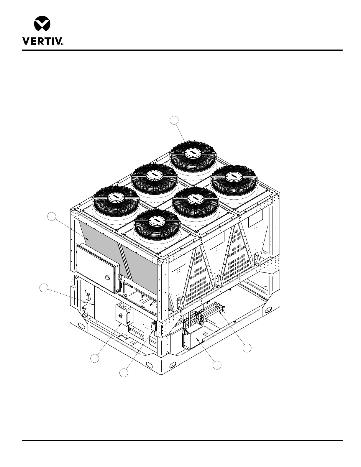
MCV430 + LIEBERT® ECONOPHASE + BASE ASSEMBLY
Form No.: DPN001040_REV4
COMPONENT LOCATION DIAGRAM
HEAT REJECTION SKID
1. Coils
2. EC Fans
3. Liebert® Econophase Pump
4. High voltage customer connection
5. Low voltage customer connection
6. Piping connections
7. 575 Volt Transformer (optional)
Note:
1.
Piping connections for entire assembly are in one
location (item 6).
2. Electrical connections for entire assembly are located
in high voltage customer connection boxes (item 4)
and low voltage customer connection box (item 5).
2
1
3
4
5
6
7