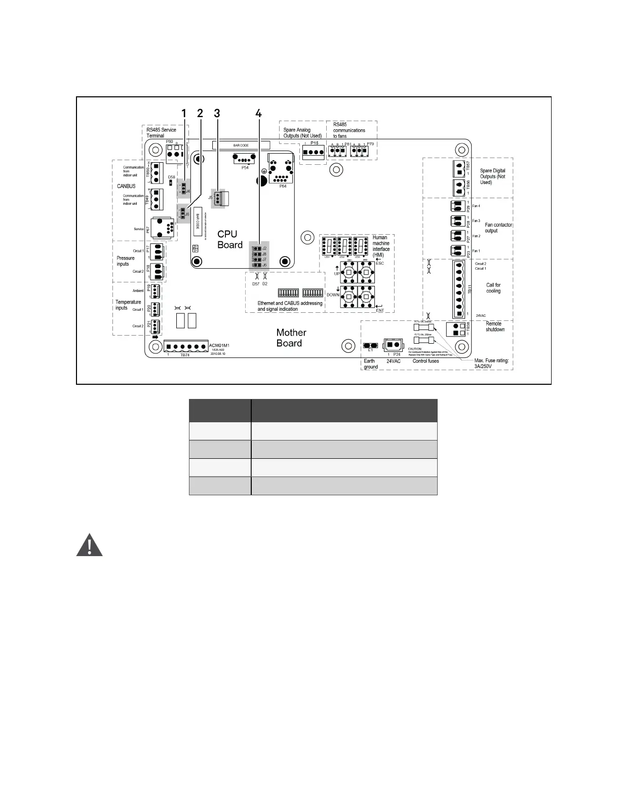
Figure 11.1 Jumper Locations on Control Board
Item Description
1 J4, RS485 service termination jumper
2 J6, CANbus termination jumper
3 J5
4 J2
11.5.2 Installing the Replacement Board
WARNING! Arc flash and electric shock hazard. Open all local and remote electric power supply disconnect
switches, verify with a voltmeter that power is Off and wear appropriate, OSHA-approved personal protective
equipment (PPE) per NFPA 70E before working within the electric control enclosure. Failure to comply can
cause serious injury or death. Customer must provide earth ground to unit, per NEC, CEC and local codes, as
applicable. Before proceeding with installation, read all instructions, verify that all the parts are included and
check the nameplate to be sure the voltage matches available utility power. The Vertiv™ Liebert® iCOM™
controller does not isolate power from the unit, even in the Unit Off mode. Some internal components require
and receive power even during the Unit Off mode of the Liebert® iCOM™ controller. The only way to ensure
that there is NO voltage inside the unit is to install and open a remote disconnect switch. Refer to unit
electrical schematic. Follow all local codes.
1. Turn Off the disconnect switch on the condenser enclosure cover.
2. Open the control enclosure cover.
11 Maintenance Proprietary and Confidential ©2024 Vertiv Group Corp. 63
Vertiv™ Liebert® MCV Installer/User Guide