Vertiv | SmartAisle2 | User Manual 43
Installation
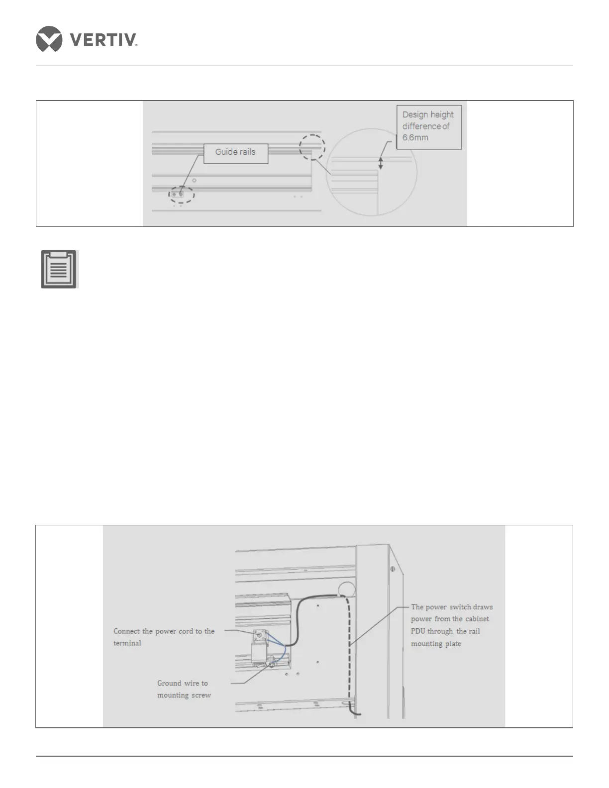
Figure 2-33 Positioning and leveling rail
• Guide rail mounted on the rim from the edge of the board is designed at a height dierence of 6.6 mm to
ensure that the mounting rail is in a horizontal state. This is done by a positioning member carrying the
cassette door in a preliminary position needs to ensure correct leveling. Adjust the exact position of the
positioning member using a screw. After the completion of the positioning, the positioning member must be
removed to avoid interference with the subsequent installation of the glass door.
• Handle the track installation carefully, else it will aect the performance and pulley life.
• The docking of the two rails should be at the center of the door, while the two rails should be kept at the
same level, horizontally and the gap between the two rails should be greater than or equal to 15 mm.
Installation of the door drive device
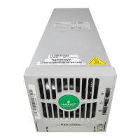
• Mounting a power switch – An upper portion of the power switching device is embedded in the trench of the
guide rail followed by embedding in the lower part of the trench wherein the position of the power switch is
at the far right of the guide rail. Tighten the mounting bolt. Route the power cable to the right of the guide rail
as shown in Figure 2-34. Connect the power cord and the power switch terminal based on the wiring diagram.
Remove the mounting bolt of the power switch and connect the ground wire at the position shown in Figure
2-34.
Figure 2-34 Mounting the power switch