Vertiv | SmartAisle2 | User Manual 44
Installation
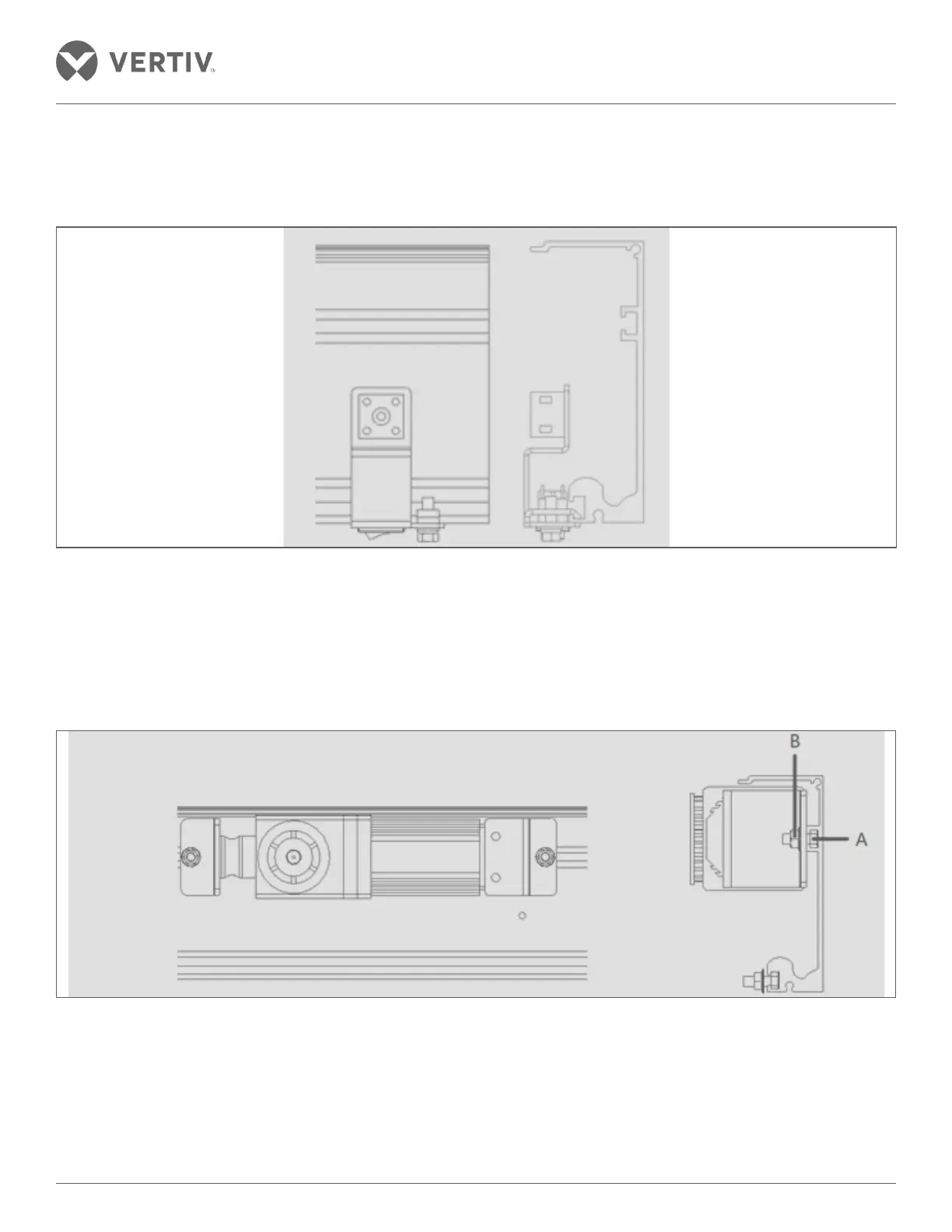
• Remove the mounting bolt of the power switch and connect the ground wire at the position shown in Figure
2-35. Insert the power switch snap into the lower groove of the rail; move the power switch to the rightmost
portion of the rail followed by tightening the mounting bolt.
Figure 2-35 Power switch installation
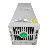
• Motor installation - Put the wire with the connector on the front of the motor. Slide the screw A from the right
to the left on the guide rail into the groove on the guide rail and place it on the right end. Then adjust the
screw spacing and the motor is mounted on the screw; Tighten the mounting nut B; place the lead wire with
the power switch through the top of the motor unit to the left of the motor unit. Ensure that the lead wire
should not be sagging.
Figure 2-36 Motor installation
• Installation Control - Slide the screw A from the left to the right in the middle of the two guide rails into the
groove on the guide rail and place it on the left side of the motor. Then, adjust the screw spacing with the
controller installed on the screw. Adjust the distance between the controller and the motor to the position
where the wires can be connected and tighten the mounting nut B.