Vertiv | SmartAisle2 | User Manual 48
Installation
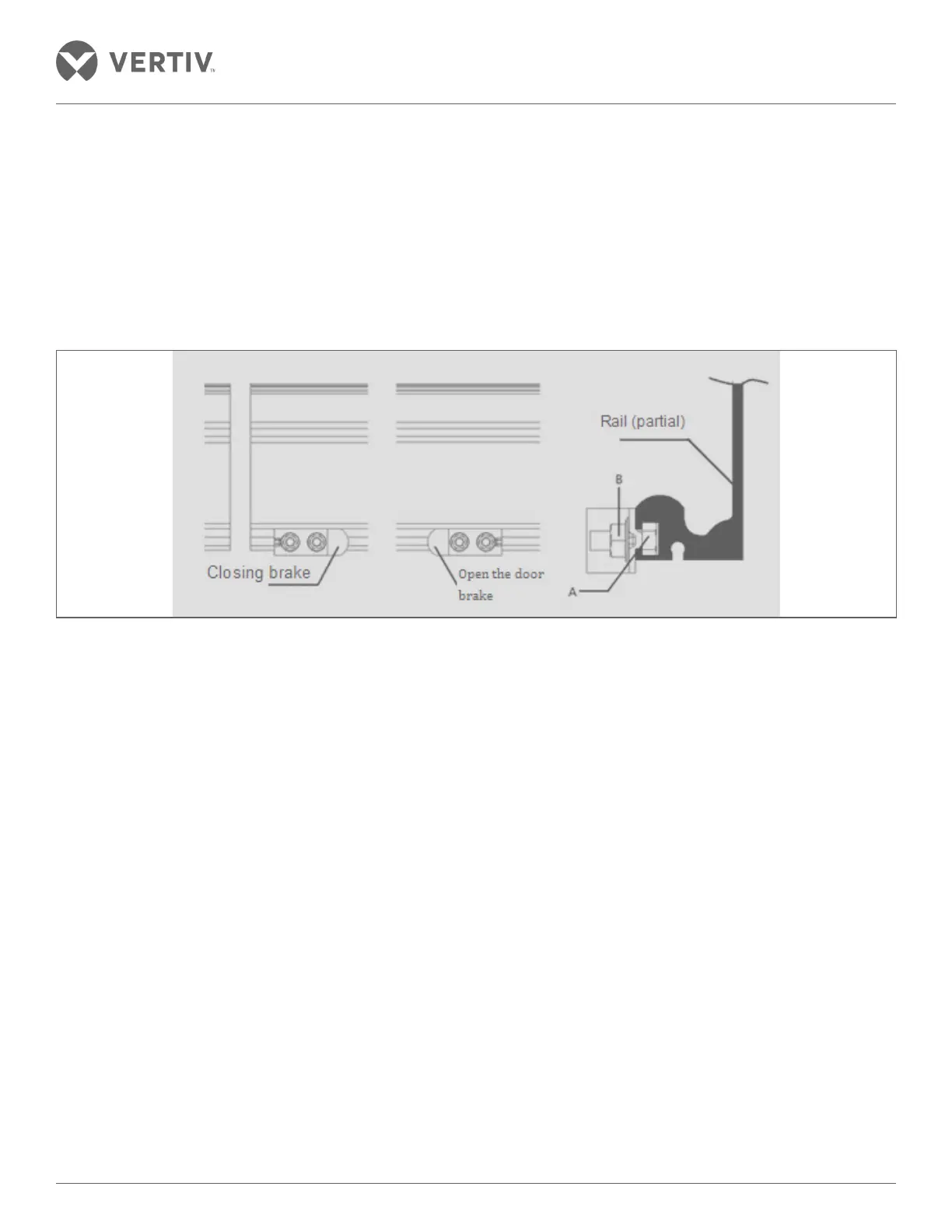
• Brake installation - The brake is installed on both sides of the right door, For the closed brake, slide the screw
A from the left to the right in the middle of the two sections of the guide rail into the lower groove of the guide
rail and place it on the left side of the right glass door hanger. For door-open brakes, slide the screw A right-
to-left from the right side of the rail into the groove under the rail and place it to the right of the right-hand
glass door hanger. Then adjust the screw spacing with the brake mounted on the screw; move the opening
and closing position of the door to determine the position of the brake device. It is advised to ensure that the
maximum opening position of the sliding doors does not go beyond the brake position. It is advised to ensure
that the maximum position of the glass door opening does not reach beyond it’s sliding point to sink inside the
door box by correctly fixing the brake position. Tighten the nut B to fix the brake position.
Figure 2-42 Brake Installation
• Belt installation - Following are the steps for fixing the belt apparatus:
» Remove bolts A (M5) to remove the belt from the belt holder fittings.
» Once the belt is removed, proceed to cut the belt. Cut o from the center of the bottom of the belt. The
length of the cut is approximately determined by the following formula:
L=(2 * DW - 100) *4 where DW is the width of a single door
» Confirm the actual size and adjust it accordingly during installation.
» The ends of the belt from the center of the crossed belt must be placed in the belt holder. Take utmost
care to ensure that the belt is not twisted during the installation.
» The belt holder is securely mounted to the belt fittings. Take into consideration the direction of the belt
holder.
» Hang the belt onto the belt pulley at the motor end and subsequently link it to the driven wheel.
» Refer to Figure 2-45 and Figure 2-46 to see the process and the mounting position of the belt fixing
device using the supplied mounting bolts (M6 X 12 with spring washers). It should be attached to the
hanger assembly securely. Use a wrench and socket spanners to tighten the bolts.
» The adjustment process is explained in the next section.
» The 2nd door should be in closed position.