ВШПА.421412.304 И1 SCIENTIFIC-PRODUCTION ENTERPRISE VIBROBIT LLC
If CanBasicDataOut flag is not equal to zero, relevant measuring channel message is transferred via
CAN2.0B interface. If all CanBasicDataOut flags are equal to zero, no messages are transferred from the module
via CAN 2.0B interface, however, the module generates acknowledgment of successful message transfer of other
modules, connected to CAN2.0B bus.
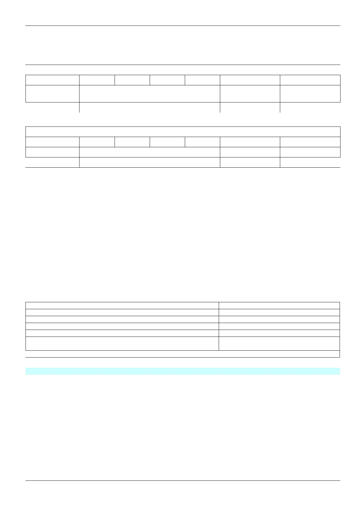
Byte number in message
0 1 2 3 4 5 6
Code Parameter measured value (4 bytes float) Measuring channel
status register
Module status
register
0x30, 0х31 Data StatusCH StatusSys
Byte number in message
0 1 2 3 4 5 6
Code Parameter measured value (4 bytes float)
0х32 Data
Figure 7. Measuring results CAN message format
I2C driven interface
I2C driven interface is designed for control of module operation and operating parameters setup. I2C interface
connector is located on the module front panel (data link connector). I2C driven interface parameters are strictly
defined, thus, independently from module current state, I2C interface is always accessible for module control.
Module setup can be implemented by means ПН31 setting unit, or PС. In order to setup by PC, dedicated
software should by run on PC and the module must be connected to PC via MC01 diagnostic interface board (RS232
Interface) or MC01 USB (USB interface).
Note. During the module setup by means of MC01 USB, virtual COM port drivers must be installed on PC
Table 12. I2C driven interface parameters
Parameter name Value
MK40 address on I2C interface 0x26
Address format for module registers reference 16 bit
Data rate, Kbit/c, not greater than 400
DC voltage at data link connector for adaptor supply, V 5±0,2
Permissible power circuit absorbed current at data link connector, mA,
not greater than
50
Galvanic isolation no
Note. Module is provided with hot swap option of setting unit and MC01, MC01 USB diagnostic interface boards
No revisions
25