Module MK40 Setup Manual
ВШПА.421412.304 И1
Logic outputs
In MK40 Module 6 logic outputs with open collector (active 0) are provided.
Logic outputs circuit design provides for possibility of direct relay coils connection.
Operation of each of 6 logic output is setup by user via digital communication interfaces.
If check sum error has been detected in one of the module operation parameters section, active signal level is
present at logic output 6, while other MK40 Module logic outputs remain in dormant state.
After module resetting, logic outputs are disabled for LogicOffStartUp period of time, counted after module
initialization cycle termination.
Logic outputs operation can be disabled by user, which may be required during module operating parameters
correction or functionality test of the module, without risk of alarm or shutoff protection trip.
MK40 Module includes “OR” matrix (LogicMatrix) for switching of status flags (of measuring channels and
general module status) to logic outputs. If at least one flag, assigned for logic output, is activated, active signal level
will be present at relevant logic output, unless logic outputs are disabled.
Number of logic output, to which it will be assigned, is indicated for each flag. If number of logic output is equal
to o or greater than 6, state of relevant assigned flag will not affect any of logic outputs.
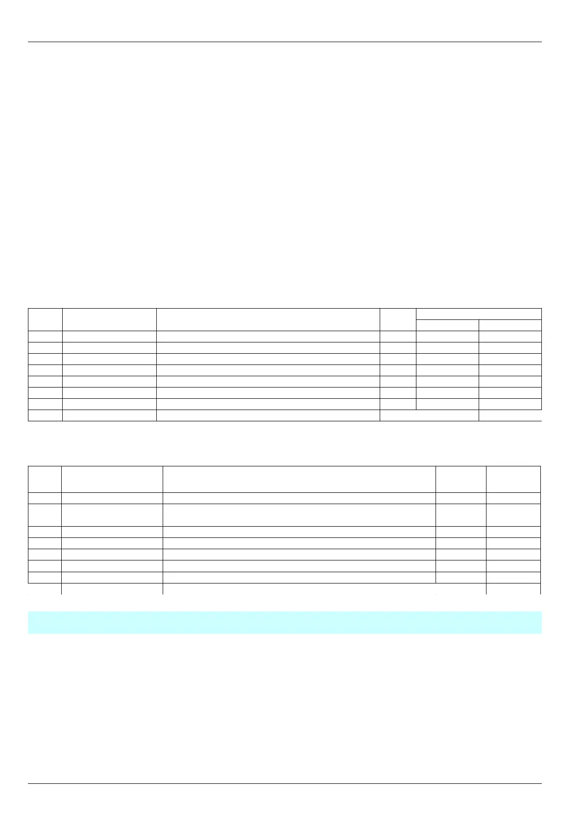
Table 5. Measuring channels status flags StatusCh and their position if logic outputs matrix LogicMatrix
Bit
No.
Label Description Code
Position in matrix
Channel 1 Channel 2
0
OffMode
Measuring channel is off Off 8 16
1
ErrorSenseLow
Sensor current below acceptable level xSL 9 17
2
ErrorSenseHigh
Sensor current above acceptable level xSH 10 18
3
FlagError
Measuring channel general fault flag xFE 11 19
4
StopMode
“STOP” mode xSM 12 20
5
OutPoint_1
Parameter value overrun of set-point 1 xS1 13 21
6
OutPoint_2
Parameter value overrun of set-point 2 xS2 14 22
7
OutPoint_3
Parameter value overrun of set-point 3 xS3 15 23
Note.
In alarm code instead of “x” symbol, channel number should be indicated (for example 1SH).
Table 6. Module status flags StatusSys and their position if logic outputs matrix LogicMatrix
Bit
No.
Label Description Code
Position
in matrix
0
ErrorLoadData
Operating parameter readout from volatile memory error ErrLD 0
1
LoadDataReserv
One or several operating parameters groups are readout
from volatile memory reserve storage
ResLD 1
2
LogicOffStartUp
Logic outputs are disabled after module resetting LgOffSt 2
3
LogicOffUser
Logic outputs are disabled by user command LgOffU 3
4
InterfRS485_Off
RS485 Interface is off RS_Off 4
5
InterfCAN_Off
CAN2.0B Interface is off CAN_Off 5
6
AllowOneWrite
Single write access is obtained OneWr 6
7
CalibrateMode
Calibration mode is on for one of standard outputs Calibr 7
Note. For changing module operating parameters, logic outputs must be disabled or permit for single write in
operating parameters must be gained.
20
No revisions