Module MK40 Setup Manual
ВШПА.421412.304 И1
Control commands
Several reserved registers are provided for control commands implementation.
Control commands are only implemented by individual writing to each register (implementation of several
commands during one transaction is not possible).
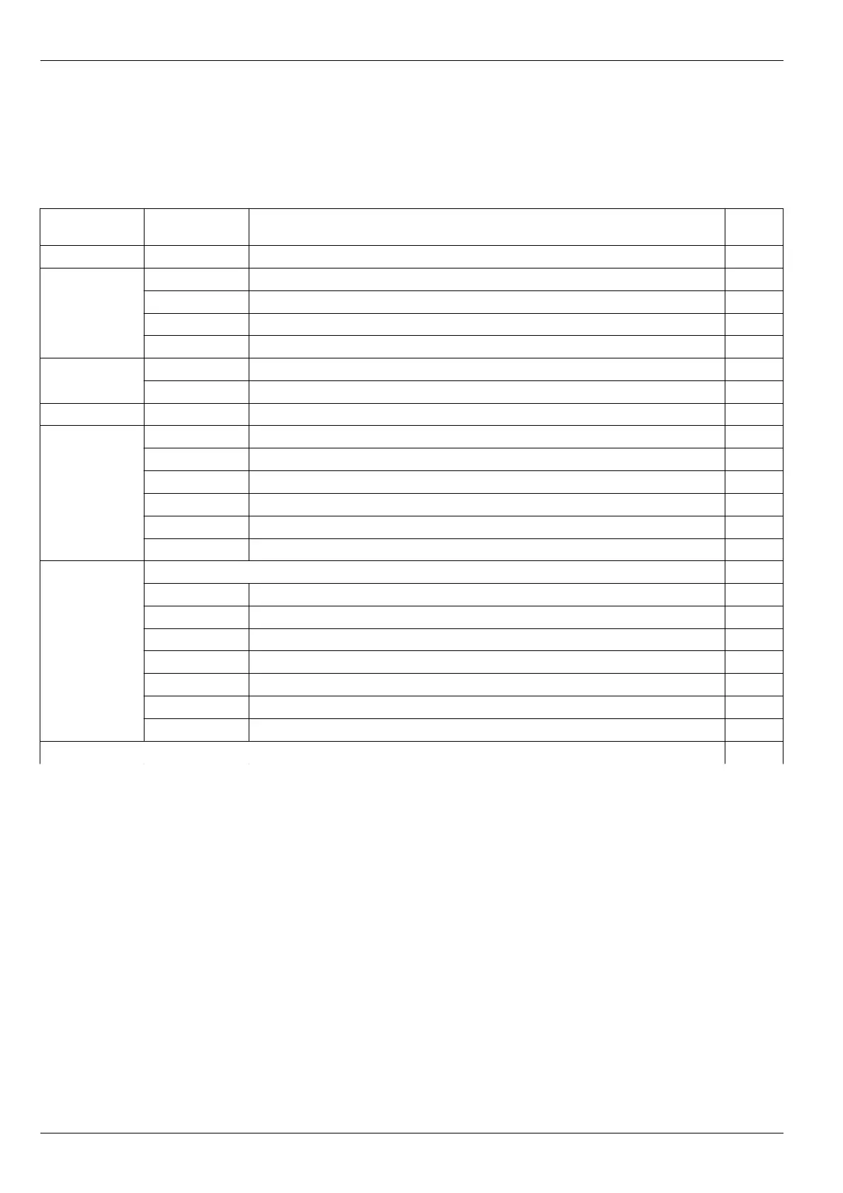
Table 23. List of control registers
Register
address (Hex)
Written value
(Hex)
Action Notes
0xFF00 0x55 Module resetting (the same as module switching on)
0xFF01 0x61 Recalculate Channel 1 ratios 1, 3
0x62 Recalculate Channel 2 ratios 1, 3
0x93 Implement RS485 interface re-initialization 2, 3
0x98 Implement CAN2.0B interface re-initialization 2, 3
0xFF02 0x33 Logic alarm disabling
0xCC Logic alarm normal operation
0xFF03 0x3C Single write query
0xFF04 0x10 Switch off test signal for both channels
0x11 Switch on test signal for channel 1
0x12 Switch on test signal for channel 2
0x50 Switch off “STOP” alarm test for channels 1, 2
0x51 Switch on “STOP” alarm test for channels 1
0x52 Switch on “STOP” alarm test for channels 2
0xFF06 Writing of module operating parameters to volatile memory 3, 4
0x81 Channel 1 calibration data
0x82 Channel 2 calibration data
0x85 Channel 1 basic parameters
0x86 Channel 2 basic parameters
0x89 Module system parameters
0x8A RS485 interface parameters
0x8B CAN2.0B interface parameters
0xFF07 0x21 Writing of all module setting parameters to volatile memory 3
Notes:
1. Can be used after module calibration for measurements check without module resetting.
2. If command is received at the time of data transfer, data is transferred completely, and then re-initialization is implemented.
3. Logic alarm must be disabled.
4. Module resetting is not implemented after writing.
5. During writing, module operation is stopped. After writing, module resetting is implemented automatically.
32
No revisions