Module MK40 Setup Manual
ВШПА.421412.304 И1
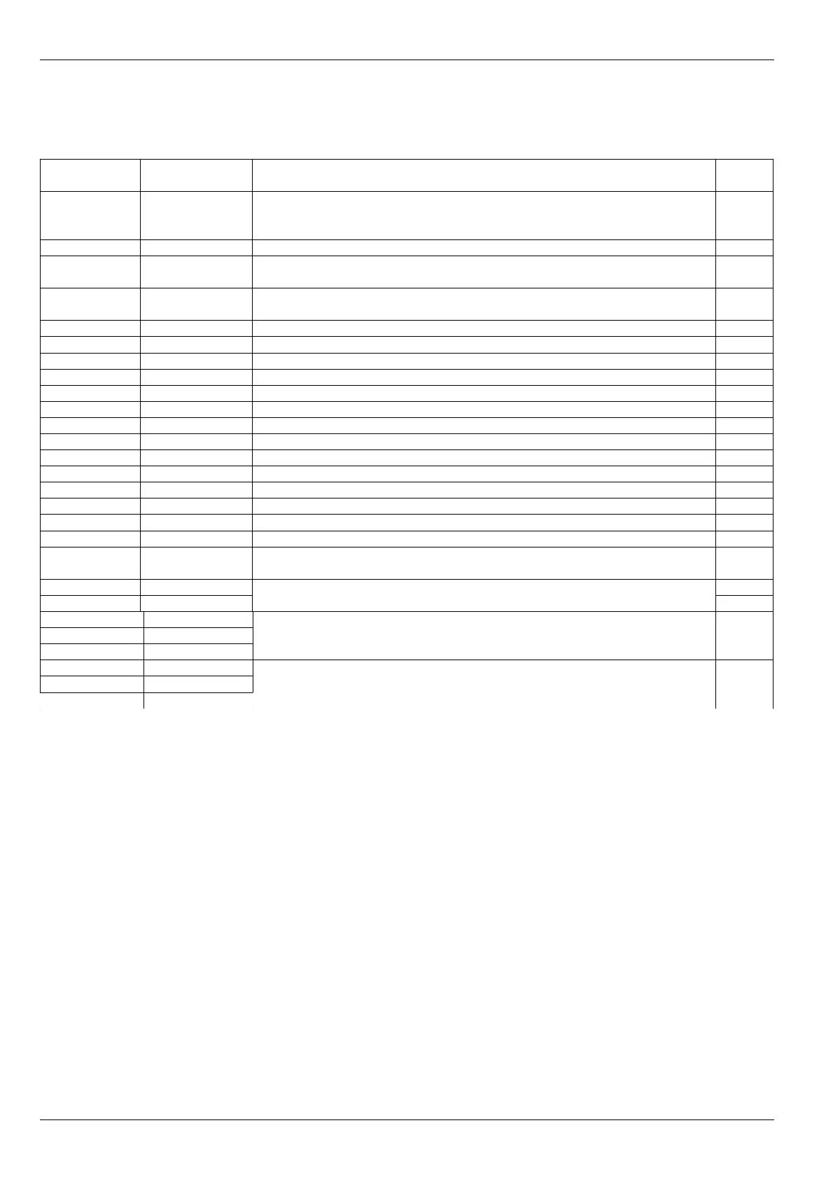
B. Connector terminals assignment
Table 24. MK40 Module X4 connector terminals assignment
Terminal
number
Label Assignment Notes
A2, B1, C2
A32, B31,
C32
GND General
A6, B5, C6 Power +24V +24V supply voltage input/output
B7 +24V sense
CH1
+24V voltage output for measuring channel 1 convertor supply 1
B9 +24V sense
CH2
+24V voltage output for measuring channel 2 convertor supply 1
C8 Input CH1 Measuring channel 1 input
C10 Input CH2 Measuring channel 2 input
B15 Analog out 1 Measuring channel 1 standard output
A16 Analog out 2 Measuring channel 2 standard output
A20, A22 Strob 1 Measuring channel 1 synchronizing pulses input
A24, A26 Strob 2 Measuring channel 2 synchronizing pulses input
B17 Test 1 Measuring channel 1 test pulse input 2
A18 Test 2 Measuring channel 2 test pulse input 2
B19 Logic out 1 Logic output 1 3
B21 Logic out 2 Logic output 2 3
B23 Logic out 3 Logic output 3 3
B25 Logic out 4 Logic output 4 3
C20, C22 Logic out 5 Logic output 5 3
C24, C26 Logic out 6 Logic output 6 3, 4
A12, B11,
C12, C18
FG Faraday grounding of AC/DC converter
Must be connected to cabinet ground.
5
C14 L220V Mains voltage AC 220V 50Hz 5
C16 N220V 5
A28 CAN-GND
B27 CAN-H
C28 CAN-L
CAN2.0B interface
A30 RS485-GND
B29 RS485-B(-)
C30 RS485-A(+)
RS485 interface
Notes:
1. +24V circuit is connected though 200mA self-healing fuse.
2. Test signal parameters must correspond to selected measuring channel input mode.
3. Operation logic is determined during module setup.
4. At read error during parameters reading from volatile memory, certain active level will be present. It is recommended to assign
all module fault signals (sensor test etc.) to this output.
5. MK40-AC-11-S option only.
6. Terminals A4, A8, A10, A14, B3, B13, C4 are not in use and must be left unconnected for compatibility with succeeding versions
of MK10.
48
No revisions