ВШПА.421412.304 И1 SCIENTIFIC-PRODUCTION ENTERPRISE VIBROBIT LLC
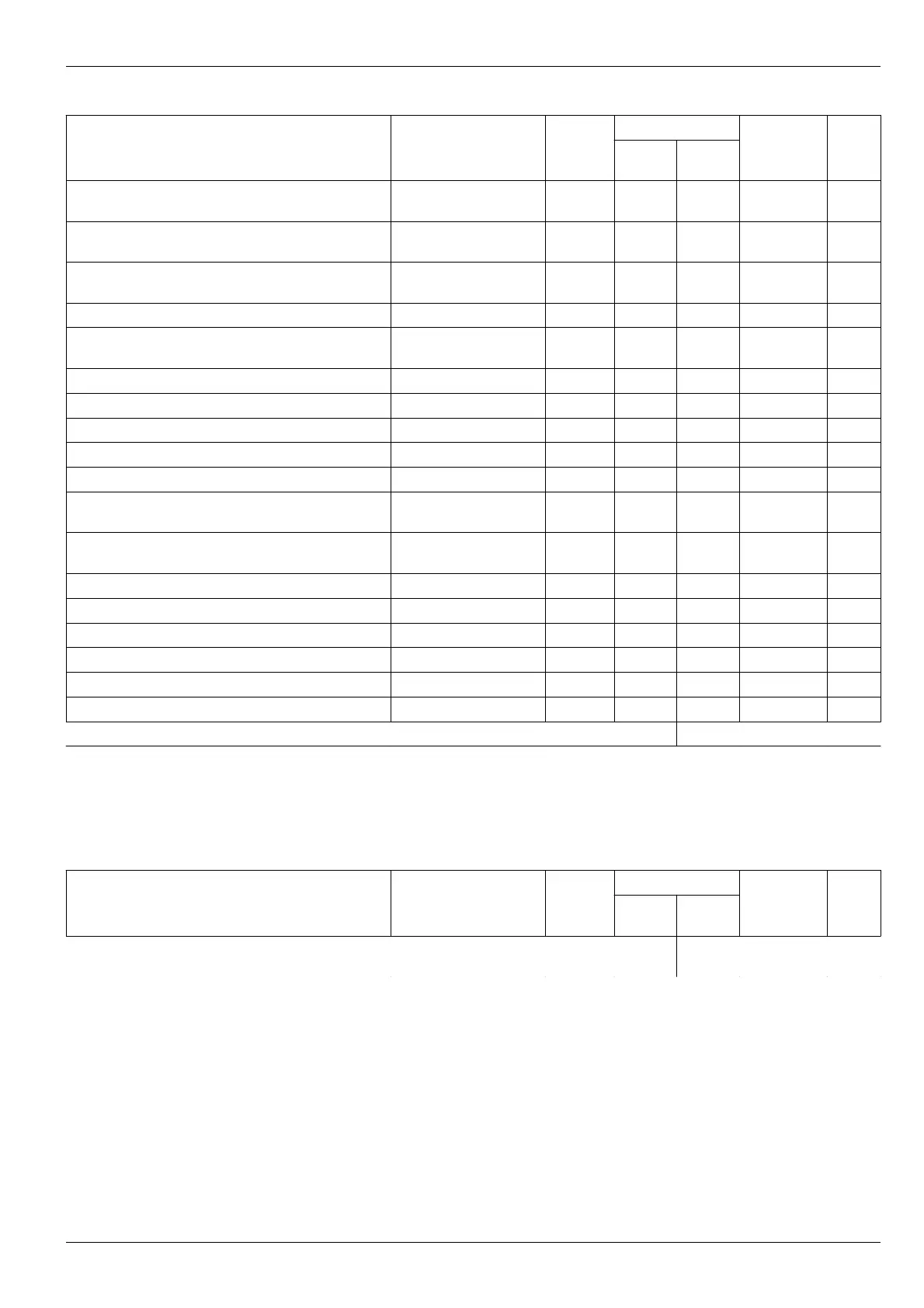
Table 14. List of measuring channels basic registers
Name Label
Type
(byte)
Address (Hex)
Channel
1
Channel
2
Default
value
Note
Measuring channel enabling
(0-channel OFF)
Enabled
Uchar (1) 0x0A00 0x0B00 1
Measuring channel operating mode
(0-starndard; 1 – voltage measurement)
ModeWork
Uchar (1) 0x0A01 0x0B01 0 1
Test signal connection enabling
(0 – disabled)
TestEnabled
Uchar (1) 0x0A02 0x0B02 1
“STOP” alarm test enabling (0 – disabled)
StopEnabled
Uchar (1) 0x0A03 0x0B03 1
Generate synchronizing pulses
(0 – generate)
PulseEnabled
Uchar (1) 0x0A04 0x0B04 0
Measured parameter lower range
RangeParamMin
Float (4) 0x0A05 0x0B05 0
Measured parameter higher range
RangeParamMax
Float (4) 0x0A09 0x0B09 4000
Minimum measured rotor speed, rpm
FrequencyMin
Float (4) 0x0A0D 0x0B0D 2.5
Pulse count per rotor revolution
Tooth
Uchar (1) 0x0A11 0x0B11 1
Data display format (0-rpm; 1 – 1000rpm)
FormatOut
Uchar (1) 0x0A12 0x0B12 0 1
Set-points test enabling in “STOP” mode
(0 – disabled)
TestPointStop
Uchar (1) 0x0A13 0x0B13 0
Set-point overrun response time
(measurement cycles)
TestPointTime
Uchar (1) 0x0A14 0x0B14 1
Set-point 1 operating mode
TestPointMode_1
Uchar (1) 0x0A15 0x0B15 0 2
Set-point 2 operating mode
TestPointMode_2
Uchar (1) 0x0A16 0x0B16 0 2
Set-point 3 operating mode
TestPointMode_3
Uchar (1) 0x0A17 0x0B17 0 2
Set-point 1
TestPointData_1
Float (4) 0x0A18 0x0B18 0
Set-point 2
TestPointData_2
Float (4) 0x0A1C 0x0B1C 0
Set-point 3
TestPointData_3
Float (4) 0x0A20 0x0B20 0
Set-point hysteresis
TestPointHist
Float (4) 0x0A24 0x0B24 0
Notes:
1. Only for MK40-DC-11, MK40-AC-11-S design options.
2. All set-points are disabled, for parameters description, refer to Table 3.
3. Default value – value assigned to parameter after the module cold start.
Table 15. List of standard output control registers
Name Label
Type
(byte)
Address (Hex)
Channel
1
Channel
2
Default
value
Note
DAC value for direct control of measuring channel
standard output
AnalogDirectData
Uint (2) 0x500 0x502 0
Notes:
1. Used in standard outputs calibration. DAC range from 0 to 4096.
2. Do not participate in channels normal operation.
3. Automatically resets to 0, if register value has not changed for 30 seconds.
4. Writable in any operating mode.
No revisions
27