Module MK40 Setup Manual
ВШПА.421412.304 И1
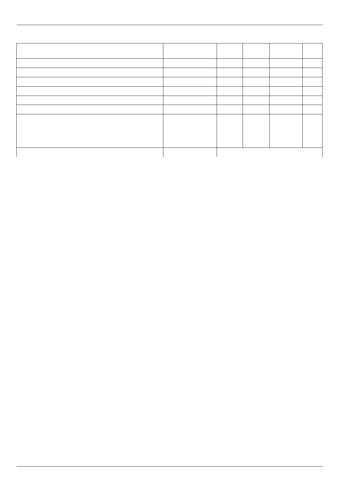
Table 16.List of system registers
Name Label
Type
(byte)
Address
(Hex)
Default
value
Notes
Logic alarm disabling time after module resetting
LogicOffStartUp
Uchar (1) 0x0E00 15 1, 3
Set-points test timeout after sensor function normalization
TestPointSenseOk
Uchar (1) 0x0E01 59 2, 3
“Measuring channel test” mode timeout.
TimeOut_TestMode
Uchar (1) 0x0E02 59 2, 3
“STOP” mode test timeout
TimeOut_TestStop
Uchar (1) 0x0E03 59 2, 3
Control modules measurement clock cycle
SynhroPulse
Uchar (1) 0x0E04 50
Set-point test timeout after sensor function normalization
PeriodMeasur
Uchar (1) 0x0E05 4 4
Logic alarm matrix
bits 0:3 – output number, to which alarm is assigned
bits 4:5– reserved, must be equal to zero
bit 6 – “War” LED is enabled for this option
bit 7 – “Alarm” LED is enabled for this option
LogicMatrix
Uchar
(24)
0x0E06 0
Signal inversion at logic output
LogicOutMode
Uchar (6) 0x0E1F 0 4
Notes:
1. In case of data read error from volatile memory, always equal to 15 (8 seconds).
2. When value is equal to zero, function is OFF.
3. Time by 0. 5s.
4. Time by 0. 1s (0 = 0.01s).
5. This parameter does not cover logic output 6.
6. Default value – value assigned to parameter after the module cold start.
28
No revisions