ВШПА.421412.304 И1 SCIENTIFIC-PRODUCTION ENTERPRISE VIBROBIT LLC
Identification information
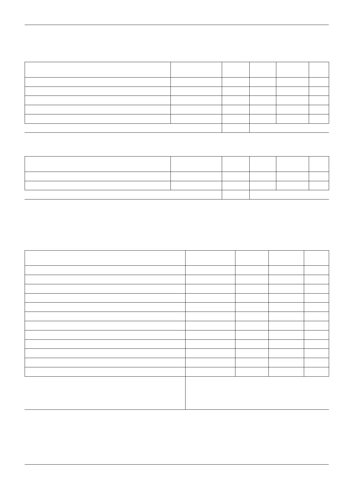
Table 20. List of module identification information registers
Name Label
Type
(byte)
Address
(Hex)
Default
value
Notes
Module serial number
Number
Uint (2) 0x1200
Module year of manufacture
Year
Uint (2) 0x1202
Order number
Order
Uint (2) 0x1204
Assembler code
Assembler
UChar (1) 0x1206
Adjuster code
Adjuster
UChar (1) 0x1207
Additional text string
TextString
Char (32) 0x1208
Note. Identification information is read-only, not initialized by cold start.
Table 21. List of module software identification information registers
Name Label
Type
(byte)
Address
(Hex)
Default
value
Notes
Microcontroller software version
Version
Char (6) 0x1300
Microcontroller software release date
Date
Char (12) 0x1306
Microcontroller software release time
Time
Char (10) 0x1312
Note. Identification information is read-only
Measurement results
Table 22. List of measurement results registers
Name Label Type (byte)
Address
(Hex)
Default
value
Rotor speed, channel 1
Data
Float (4) 0x000
Maximum rotor speed, channel 1
DataMax
Float (4) 0x004
Channel 1 status flags
StatusCh
Uint (2) 0x008
Channel 1 sensor DC current
Current
Float (4) 0x00A 1
Channel 1 ADC constant value (used for calibration0
AdcConst
Uint (2) 0x00E
Rotor speed, channel 2
Data
Float (4) 0x010
Maximum rotor speed, channel 2
DataMax
Float (4) 0x014
Channel 2 status flags
StatusCh
Uint (2) 0x018
Channel 2 sensor DC current
Current
Float (4) 0x01A 1
Channel 2 ADC constant value (used for calibration0
AdcConst
Uint (2) 0x01E
Module system flags
StatusSys
UChar (1) 0x020 2
Additional system flags
StatusSysAdd
UChar (1) 0x021
Logic outputs state
bits 0-5 – 1-6 logic outputs state
bits 6-13– reserved, equal to zero
bit 14 – “War” LED state
bit 15 – “Alarm” LED state
LogicOutStatus
Uint (2) 0x022 3
Notes:
1. For flags assignment, refer to Table 5.
2. For flags assignment, refer to Table 6.
3. During logic outputs disabling, logic outputs state after enabling can be determined.
No revisions
31