Module MK40 Setup Manual
ВШПА.421412.304 И1
Calibration
Input and standard output calibration is carried out by means of calibration wizard. Calibration operations are
accessible when MK40 Module is connected and logic outputs are disabled.
For input and output calibration, select Measuring channels option in Parameters Menu. Calibration will be
carried out for selected measuring channel.
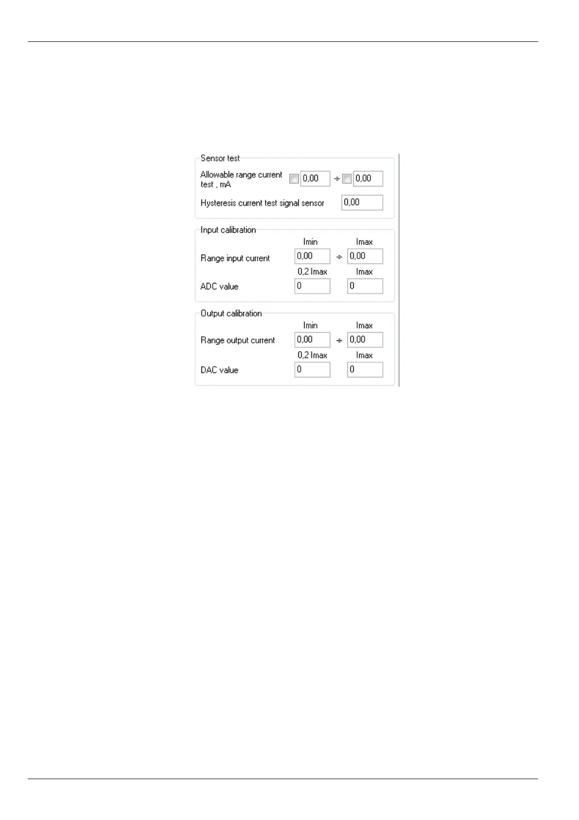
Figure 10.
Measuring channel calibration
parameters
For calibration parameters setup, act as follows:
•
Enable/disable sensor current higher/lower range test;
•
Set acceptable sensor current range;
•
Set sensor current hysteresis.
Input calibration
In order to launch input calibration wizard, select Input calibration option in Calibration Menu of Measuring
channels window. Then, following the hints, act as follows:
•
Set input current range; calibration minimum calibration current is set automatically (0.2 I
max
);
•
Minimum calibration current must be supplied at actual channel input;
•
After setting ADC value, maximum range current must be supplied at the input;
•
After pressing of Continue push button, acquired data is saved in actual channel setup window;
•
For ratios recalculation in module, actual channel settings must be saved to MK40 Module and press
ratios recalculation push button;
At latter stage of calibration, obtained ADC values can be edited. Cancel push button can be pressed at any
stage in order to abort calibration.
36
No revisions