Module MK40 Setup Manual
ВШПА.421412.304 И1
D. Module (Setup) Order Form example
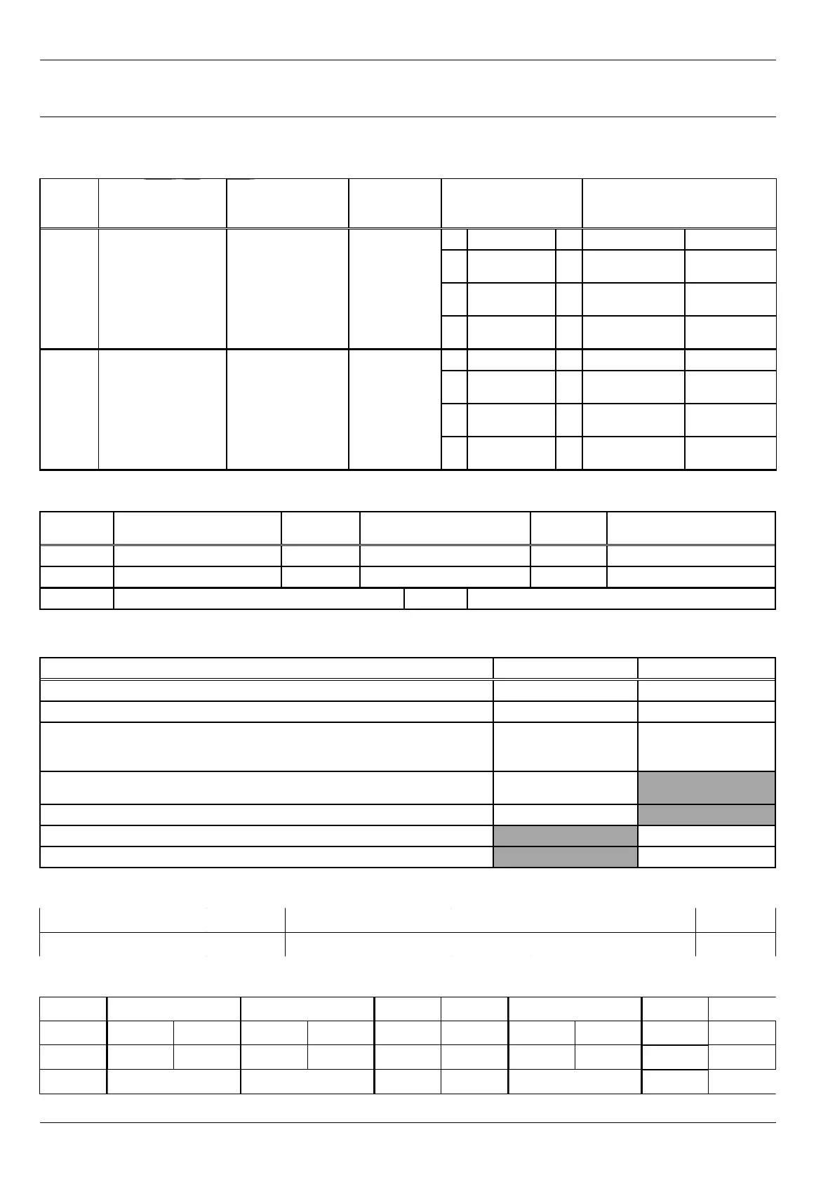
МК40 Module (Setup) Order Form
Module design option (DC; DC-11, DC-001, AC-11-S) ______ Quantity of modules with actual setup ______
1. Measuring channels parameters
Chan
nel
No.
Brief description
Sensor/
transducer
Parameter
range
Set-points
parameters
Additional
parameters
1. 1
Teeth
2
Set-point
hysteresis
3
Standard
output
Minimum
rotor speed
2. 1
Teeth
2
Set-point
hysteresis
3
Standard
output
Minimum
rotor speed
2. Logic alarm parameters and “War”, “Alarm” LED’s on the module front pane
Channel
No.
Logic formula
Channel
No.
Logic formula
Channel
No.
Logic formula
1. 3. 5.
2. 4. 6.
War Alarm
Operations
:
‘()’ – group selection «OR» ‘+’ – operation “OR”
'!' – logical inversion
3. RS485, CAN interfaces parameters
Parameter
RS485 interface CAN interface
Enable interface operation
Module address (RS485 – from 1 to 247; CAN – from 0 to 65535)
Date exchange rate
RS485 – 4800, 9600, 19200, 38400, 57600, 115200, 230600 bit/s
CAN – 40, 80, 100, 125, 200, 250, 500, 1000 Kbit/s
Enable changes by commands from communication interfaces
(Yes/No)
Enable single write command support (Yes/No)
Message sending interval, s (CAN only)
Enable data transfer in measuring channels
4. Module additional parameters (values different from default values)
Parameter Value Parameter Value Parameter Value
5. Bridges position on MK40 board (OFF, ON, 1-2, 3-4)
Bridge Position Bridge Position Bridge Position Bridge Position Bridge Bridge
Channel 1
S1 S12 S3 S7 S6
Channel 2
S2 S13 S4 S8 S5
Common
S9 S10 S11
Prepared by ________________ Date _____________________
50
No revisions