ВШПА.421412.304 И1 SCIENTIFIC-PRODUCTION ENTERPRISE VIBROBIT LLC
Comparing measured parameter value with set-point value
If FlagError flag is dropped (wait timeout is counted after sensor operation normalization), calculated rotor
speed value of is compared with set-points values, set during the module setup.
If sensor fault has been detected (one of ErrorSenseLow, ErrorSenseHigh flags is activated) or
FlagError flag is activated, comparison of calculated D
Param
value with set-points values is not implemented, and all
measured parameter value overrun flags are dropped.
Four set-points are provided for each measuring channel (TestPointData) with individually setup operating
modes (TestPointMode), general hysteresis level (TestPointHist) and overrun response time
(TestPointTime).
Table 3. Set-points operating modes
Mode code Description
0 Set-point is disabled, test is not carried out
1 Test above set-point value
2 Test below set-point value
Operating mode – set-points are disabled
Rotor speed value is not compared with TestPointData set-point, OutPoint flag is always dropped.
Operating mode - test above set-point value
If rotor speed value is higher than TestPointData set-point within TestPointTime time, parameter level is deemed
too high and OutPoint flag is activated. In order to drop OutPoint flag (normal level), rotor speed value must be lower
that TestPointData-TestPointHist within TestPointTime time.
Operating mode - test below set-point value
If rotor speed value is lower than TestPointData set-point value within TestPointTime time, parameter level is
deemed too low and OutPoint flag is activated. In order to drop OutPoint flag (normal level), rotor speed value must be
higher that TestPointData+TestPointHist within TestPointTime time.
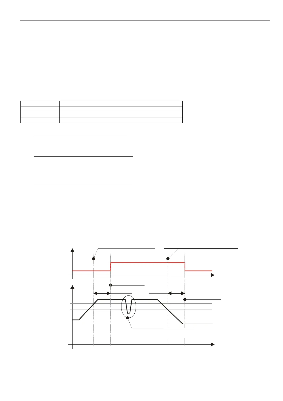
Figure 5 shows an example of alarm function at set-point 2400rpm and hysteresis of 100prm.
Set-points test enabling in “STOP” mode is determined by StopEnabled parameter. If StopEnabled parameter is
equal to zero, in “STOP” mode rotor speed value (equal to 0) is not compared with set-points, rotor speed overrun
flags are inactive.
Figure 5. Example of set-point algorithm
(mode – test above set-point level).
No revisions
15
OutPoint
Time TestPointTime
Flag
Logic
level
Detected output value of
the parameter for set point
Value of parameter is less set
point taking into account a hysteresis
Time
Time
Signaling switching-on
Signaling switching-off
Short-term surge doesn't
cause signaling switching
Freq, rpm
2400
2500