ВШПА.421412.304 И1 SCIENTIFIC-PRODUCTION ENTERPRISE VIBROBIT LLC
Indication and control equipment
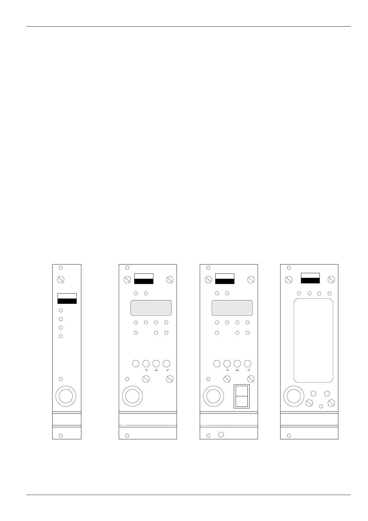
The front panel features of MK40 Module vary depending on design option. Appearance of MK40 Module front
panels is shown in Figure 1.
The following elements are arranged on all front panel types:
•
handle for module installation/dismantling in framework;
•
captured screws;
•
diagnostic interface D.port connector;
•
hidden Reset key for the module resetting;
•
Module state indication Ok LED.
Module state can be assessed based on Ok LED emission color:
▪
Green light – normal module operation;
▪
Yellow light – output logic alarm is disabled by user or after the module resetting;
▪
Red light – fatal error in module operation, module operation is disabled;
▪
Green (yellow) light flashing – sensor test error is detected for one of measuring channels.
MK40-DC
design option
Narrow front panel (width - 20mm) with restricted indication display and control system. Measurement results
review is only possible at reading via digital communication interfaces. Additionally, on the module front panel are
arranged:
•
“Pwr” green LED – module switching on;
•
“Ok” bicolor LED – module status indication;
•
“War” yellow LED – warning (LED operation logic is defined by user);
•
“Alarm” red LED – alarm (operation logic is defined by user).
а) MK40-DC б) MK40-DC-11 в) MK40-AC-11-S г) MK40-DC-001
Figure 1. MK40 Module front panel appearance
No revisions
7
D.port
Reset
об/мин
ВИБРО
БИТ
MK40
С1
С2
Stop
∇1 ∇2 ∇3
Ok
Err Max
Sel
ch
Sel
∇
Max
freq
Logic
off
T-st T-ch
D.port
Reset
Ok
Pwr
War
ВИБРО
БИТ
MK40
Alarm
D.port
Reset
об/мин
ВИБРО
БИТ
MK40
С1
С2
Stop
∇1 ∇2 ∇3
Ok
Err Max
Sel
ch
Sel
∇
Max
freq
Logic
off
T-st T-ch
Power
ON
D.port
Reset
Ok
Pwr War
ВИБРО
БИТ
MK40
Alarm
Mode Sel