ВШПА.421412.304 И1 SCIENTIFIC-PRODUCTION ENTERPRISE VIBROBIT LLC
C. Module labeling
Module labeling comprises:
•
MK40 Module type and design option (DC, DC-11, DC-001, AC-11-S);
•
Module serial number and year of manufacture;
•
Standard outputs operating mode (A – 1-5mA; B – 4-20mA);
•
Assembler number;
•
Adjuster number;
•
Order number.
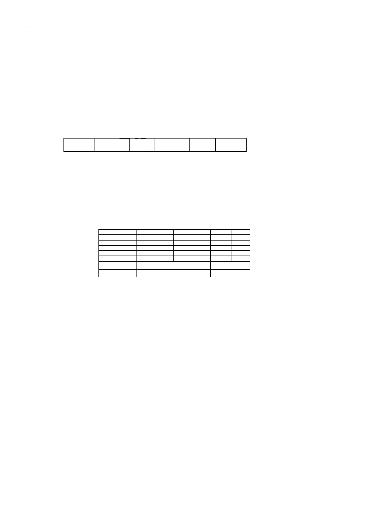
Example of module labeling
МК40
DC-11
Module No.
-
Mode Assemble. Adjust. Order
Detailed information on module setting up (measuring ranges, set-points levels in measuring channels,
communication interfaces parameters, logic alarm setup etc.) is stipulated in relevant module Setting up report.
Additionally, a label with module basic settings is attached to module board.
Example of basic settings label on the module board.
Channel 1 2 3 4
Unit rpm rpm
Range 0-6000 0-6000
Set-point1
Set-point2
Set-point3
RS485 Address 014 Rate 115200 Address 014
CAN2.0B Address Rate Address
No revisions
49