Module MK40 Setup Manual
ВШПА.421412.304 И1
Rotor speed measurement
Rotor speed measurement is implemented, providing that sensor fault was not detected (ErrorSenseLow,
ErrorSenseHigh flags are dropped). If sensor fault was detected (one of ErrorSenseLow, ErrorSenseHigh
flags is activated), rotor speed is not calculated and taken as equal to zero.
Note. Synchronizing pulses are generated (if enabled in the module settings), even if sensor fault was detected.
Definition of rotor speed is implemented by measuring of clock cycles, calculation of leading edge of timing
signal with frequency 10MHz between two clock cycles active fronts.
Clock cycle value is averaged during measurement cycle (determined by PeriodMeasur parameter), then rotor
speed is calculated in rpm (with provision for preset number of pulses per rotor revolution).
If only one clock cycle was detected during measurement cycle, non-averaged clock cycle value is used in rotor
speed calculation.
Minimum measured rotor speed is set by FrequencyMin (not less than 0.9 rpm). If rotor speed is below preset
value, synchronization pulses are deemed non-existing (rotor is stopped).
Synchronizing pulses polarity
Active front polarity of input pulses and repeated synchronizing pulses is determined by bridges on the module
board (see Annex A).
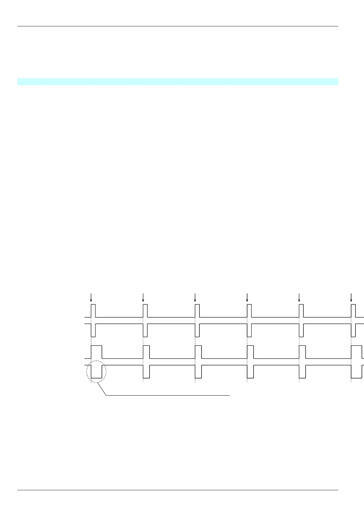
In Figure 4 are shown input/output synchronizing pulses diagrams for 1
st
measuring channel depending on
bridges position on the module board (same for 2
nd
measuring channel).
Synchronizing pulses are generated only if enabled in the module settings (PulseEnabled parameter).
Other ASVM modules synchronization (calculation of rotational components and phases) by MK40 Module input
signals must only be implemented at bridges selected active front, as inactive front of repeated synchronizing pulses
has jitter not greater than ±200mks (output synchronizing pulse duration 800-1000mks).
In order to synchronize simultaneous results acquisition by ASVM control modules, MK40 Module generates
synchronizing pulses with twofold duration and SynchroPulse time (if SynchroPulse is equal to zero, lengthened
synchronizing pulses are not generated).
Figure 4. Polarity of input and output synchronizing pulses
14
No revisions
Широкий импульс
синхронизации измерений (SynhroPulse = 5)
Активный фронт
Входные
импульсы
Выходные
импульсы
S3 (2-3)
S3 (1-2)
S7 (1-2)
S7 (2-3)
Note. It is implied, that adjusting resistor is connected to positive supply of pulse output.
Rate of pulse rise is determined by output circuit capacitance and
adjusting circuit parameters (resistor resistance, adjustment voltage).
Rate of pulse rise is determined by output circuit capacitance and
adjusting circuit parameters (resistor resistance, adjustment voltage).