ВШПА.421412.304 И1 SCIENTIFIC-PRODUCTION ENTERPRISE VIBROBIT LLC
Sensor functionality test
Sensor test is carried out by I
sense
calculated value. Sensor is deemed functional, if value falls within acceptable
limits (CurrValidMin, CurrValidMax), setup during the module settings.
Monitoring of minimum/maximum acceptable sensor current can be disabled in the module settings
(EnaValidMin, EnaValidMax respectively). If sensor current monitoring is switched off at one of the limits, sensor
is deemed functional independent of calculated sensor current.
Enabling of sensor current monitoring can be useful, for example, during MK40 Module operation with sensor
signals level 0-5mA; in this case, disabling of sensor current lower limit monitoring is reasonable.
If I
sense
value is lower than minimum acceptable current level CurrValidMin, sensor signal level is deemed too
low (ErrorSenseLow, FlagError flags are activated). In order to normalize measuring channel function, I
sense
value must be higher than CurrValidMin + CurrValidHist (ErrorSenceLow flag is dropped).
If I
sense
value is higher than maximum acceptable current level CurrValidMax, sensor signal level is deemed
too high (ErrorSenseHigh, FlagError flags are activated). In order to normalize measuring channel function,
I
sense
value must be lower than CurrValidMin - CurrValidHist (ErrorSenceHigh flag is dropped).
When any abnormal sensor current level flag is activated (ErrorSenseLow, ErrorSenseHigh), measured
parameter value is taken as equal to zero.
It is not recommended to set sensor current level hysteresis value (CurrValidHist) equal to zero, as the
alarm frequent switch-over effect may occur.
After normalization of sensor function and ErrorSenseLow, ErrorSenseHigh flags are dropped, FlagError
flag is dropped after definite time interval TestPointSenseOK. After FlagError flag drop, calculated value of
measured parameter is compared with set-point.
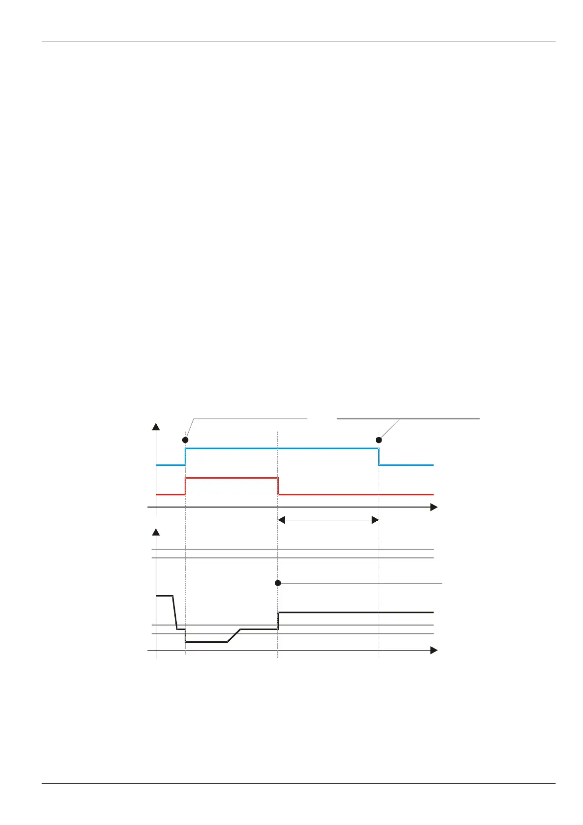
In Figure 3 is shown an example of sensor test algorithm during sensor constant current decrease below
acceptable level. Sensor current acceptable levels are equal to 0,9mA and 5,1mA respectively, hysteresis – 0,1mA.
Figure 3. Sensor test algorithm during sensor constant
current decrease below acceptable level
After the module resetting, sensor is deemed functional, however timeout is to be counted before comparing
parameter value with set-points value, as FlagError flag is automatically activated after resetting.
No revisions
13
ErrorSenseLow
FlagError
0,9
1,0
5,1
5,0
Time TestPointSenseOk
Malfunction of the sensor is found
out, the parameter is equal to zero
Comparing of value of
parameter with set point is authorized
Flag
Logic
level
Sensor
Current,
mA
Sensor operation was normalized,
the measured parameter is calculated
Time
Time