134
F.865 Refrigerant circuit high pressure shutdown
F.865
System characteristics
Refrigerant circuit off
Cause
High pressure fault:
■
Air in the secondary circuit
■
Secondary circuit or integral heating/cooling circuit
shut off
■
Secondary circuit pump or integral heating/cooling
circuit pumps blocked or faulty
■
Condenser contaminated
■
High pressure sensor faulty
■
Set flow temperatures for room heating/room cooling
or DHW heating too high
Measures
1. Ensure that all Schrader valves are open.
2. If necessary, vent secondary circuit. Check secon-
dary circuit pump for dirt (impeller) and correct func-
tion.
3. Ensure the minimum flow rate.
4. Clean filter in ball valve of outdoor unit. If necessary,
check heating filter with magnetite separation.
5. To check the high pressure sensor, check voltage
at X14.1 to X14.2 on VCMU refrigerant circuit con-
troller (0 to 5 V).
6. Check refrigerant charge in refrigerant circuit.
7. Check condenser for contamination. If necessary,
remove and flush out.
8. Check electronic expansion valve for correct func-
tion. If necessary, remove and flush out.
F.866 Refrigerant circuit low pressure shutdown
F.866
System characteristics
Refrigerant circuit off
Cause
Low pressure fault:
■
Lack of refrigerant.
■
Evaporator contaminated
■
Fan blocked or faulty
Measures
1. Check free rotation of fan.
2. Check fuse on mains terminal of fan.
3. Check refrigerant charge in refrigerant circuit.
4. Reduce defrost interval. Increase defrost stop tem-
perature.
5. Check electronic expansion valve for correct func-
tion. If necessary, remove and flush out.
6. Clean the evaporator.
7. Open service valve on low pressure side (Schrader
valve). If necessary, check for correct function.
8. Check refrigerant circuit lines for damage.
9. Take action as necessary depending on further fault
messages.
F.875 Communication error with connected main appliance
F.875
System characteristics
Limited operation of the heat pump cascade
Cause
Communication error with (lead) heat pump (main
appliance)
Measures
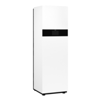
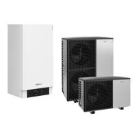
Check the following CAN bus connections:
■
Connection X8.1 to X8.3 on plug 91 on HPMU elec-
tronics module
■
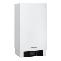
Wall mounted indoor unit:
Connection on device underside, 6-pole connection
socket on the left, terminals 1.CAN L to 3.CAN H
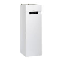
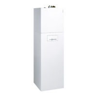
Floorstanding indoor unit:
Connection to luster terminals for BUS connections,
terminals 91.CAN L to 91.CAN H
■
Connections to the other CAN bus subscribers
■
Check wires and plugs for correct seating.
■
Check connections for contact corrosion.
Messages
Fault messages (cont.)
6218234
Diagnosis





 To Next Page