24
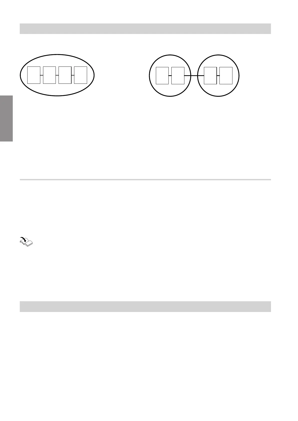
Example: Inverter cascade
Fig. 2
A
Inverter cascade consisting of Vitocharge VX3
units
B
Main appliance: Vitocharge VX3 with the highest
capacity as the master inverter
C
Further Viessmann appliance: Vitocharge VX3 as
a slave inverter
D
Further Viessmann appliance: Vitocharge VX3 as
a slave inverter
E
Further Viessmann appliance: Vitocharge VX3 as
a slave inverter
Example: Heat pump cascade in a system network
Fig. 3
A
Heat pump cascade
B
Main appliance: Master heat pump
C
Further Viessmann appliance: Slave heat pump
D
Further Viessmann appliances outside the heat
pump cascade
E
Further Viessmann appliance: e.g. Vitocharge VX3
F
Further Viessmann appliance: e.g. Vitoair
Commissioning the CAN bus subscribers in a system network
In a system network, all Viessmann appliances with
One Base are commissioned using the ViGuide app
via the access point of the main appliance. With some
Viessmann appliances, commissioning can alterna-
tively be started on the programming unit of the main
appliance using the commissioning assistant.
Installation and service instructions of the
Viessmann appliance
■
The Viessmann appliance on which commissioning
is started is automatically the main appliance.
The communication module of the main appliance is
used to commission and operate the other Viess-
mann appliances.
The other Viessmann appliances recognise the con-
nection to the main appliance and display this on
their programming unit.
■
In conjunction with a heat pump, commissioning
must always be started at the (master) heat pump.
If another Viessmann appliance from the system net-
work was already in operation, restore the factory
settings on this appliance first. Then start commis-
sioning on the (master) heat pump.
■
If another Viessmann appliance is commissioned
later, the main appliance is recognised automatically.
Defrost
During the normal operation of air source heat pumps,
water from the ambient air condenses on the evapora-
tor. The defrost function minimises ice formation at low
outside temperatures. The aim of the defrost process
is to dry the evaporator.
The defrost function is preset at the factory and cannot
be deactivated. Air source heat pumps are only defros-
ted by reversing the refrigerant circuit.
The following operating data determines the start of
the defrost process:
■
Evaporation temperature
■
Compressor speed
■
Air intake temperature
A heat pump-specific performance map is stored in the
control unit for this operating data. The defrost process
is activated when the current values are at certain
positions in relation to the performance map.
For defrosting, the heating water volume and therefore
the thermal energy of the following components are
used:
■
Buffer cylinder integrated in the indoor unit
■
Condenser in the outdoor unit
■
Hydraulic connection lines between indoor and out-
door unit
Function description
CAN bus system (cont.)
6218234
Functions