45
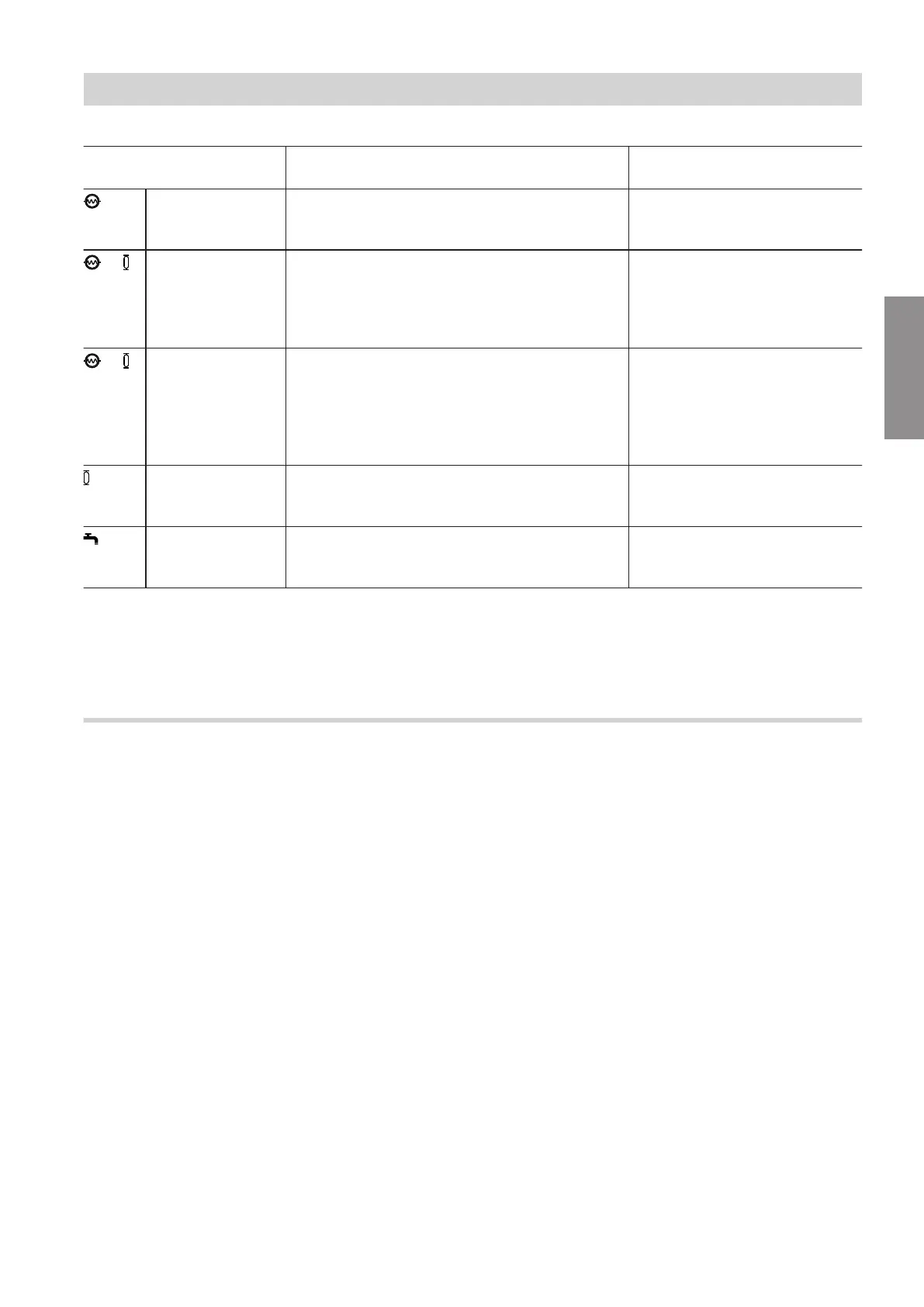
Overview of system components that receive a flow
Position of 4/3-way valve Indoor unit with 1 integral heating/cooling
circuit
Indoor unit with 2 integral
heating/cooling circuits
0 V to 0.5 V
≙
0 % to < 5 %
Secondary circuit (heating/cooling circuit 1 or
external buffer cylinder)
Heating/cooling circuit 1
— From 0.5 V
≙
≥ 5 % to ≤ 25 %
Mixed operation:
■
Secondary circuit (heating/cooling circuit 1 or
external buffer cylinder)
and
■
Integral buffer cylinder
Mixed operation:
■
Heating/cooling circuit 1
and
■
Integral buffer cylinder
— Up to 7.9 V
≙
> 25 % to < 50 %
Mixed operation:
■
Secondary circuit (heating/cooling circuit 1 or
external buffer cylinder)
or
■
Defrost
Mixed operation:
■
Heating/cooling circuit 1
or
■
Defrosting
or
■
Heating/cooling circuit 2
8 V
≙
50 %
Integral buffer cylinder
■
Integral buffer cylinder
or
■
Heating/cooling circuit 2
10 V
≙
≥ 95 % to 100 %
DHW heating DHW heating
Note
If the 4/3-way valve is faulty, no voltage is present.
This means that the 4/3-way valve is in the 0 % to
< 5 % position. Therefore, only heating/cooling circuit 1
is supplied.
Minimum flow rates
■
Between the indoor and outdoor unit:
Using the 4/3-way valve, a minimum flow rate of
> 300 l/h is set under all operating conditions.
■
Heating/cooling circuits:
Using the 4/3-way valve, a minimum flow rate of
> 300 l/h is set under all operating conditions.
■
Instantaneous heating water heater:
The minimum flow rate required for the instantane-
ous heating water heater depends on the required
output stage:
Stage 1: 250 l/h
Stage 2: 425 l/h
Stage 3: 600 l/h
Note
If the flow rate in the secondary circuit is lower than
the specified values, a lower stage may be switched
on.
■
Defrosting:
The defrost process requires a minimum flow rate of
900 l/h.
Note
The heating/cooling circuits are not supplied with
heat during defrosting.
■
DHW heating:
Minimum flow rate depends on the DHW cylinder.
Function description
Flow rate control with Hydro AutoControl (cont.)
6218234
Functions