27
■
Heat pump with integral instantaneous heating water
heater:
If the output available from the outdoor unit is not
sufficient, the instantaneous heating water heater is
switched on in stages.
If the duration determined for buffer heating has
expired but the required minimum return temperature
has not yet been reached, all stages of the instanta-
neous heating water heater are switched on.
■
Systems with external heat generator:
If the output available from the outdoor unit is not
sufficient, the external heat generator is switched on.
■
Systems with external heating/cooling water buffer
cylinder:
If the output available from the outdoor unit is not
sufficient, the thermal energy from the external buffer
cylinder is used.
Heating of the integral buffer cylinder ends as soon as
the minimum return temperature is 2 K above the cal-
culated set value.
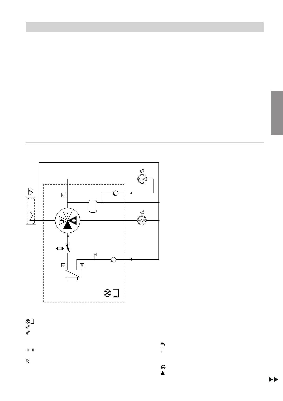
Defrost process
Flow diagram
Fig. 5 Example of defrosting via heating/cooling cir-
cuit 1
Air source heat pump
Heating/cooling circuit 1
Indoor unit with 2 integral heating/cooling cir-
cuits:
Heating/cooling circuit 2
Instantaneous heating water heater
(not available with all heat pump types)
DHW cylinder
(integrated in floorstanding indoor units)
A
Return temperature sensor, secondary circuit
B
Condenser
C
Flow temperature sensor, secondary circuit
D
4/3-way valve
Positions:
DHW heating
Integral buffer cylinder
For indoor unit with 2 integral heating/cooling
circuits, also heating/cooling circuit 2
Heating/cooling circuit 1
Open flow direction
Function description
Defrost (cont.)
6218234
Functions
 Loading...


