26
Heating the integral buffer cylinder
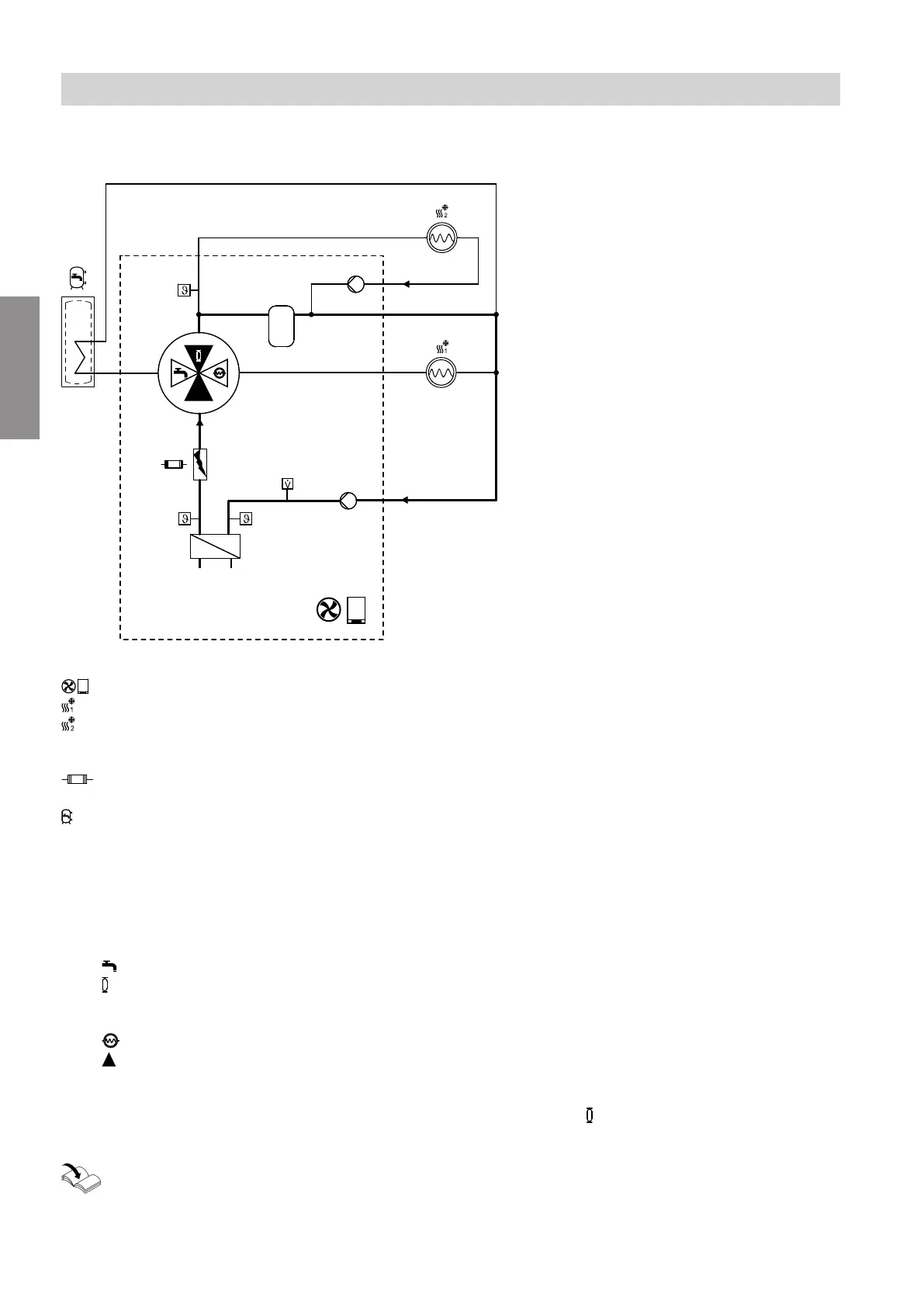
Flow diagram
Fig. 4
Air source heat pump
Heating/cooling circuit 1
Indoor unit with 2 integral heating/cooling cir-
cuits:
Heating/cooling circuit 2
Instantaneous heating water heater
(not available with all heat pump types)
DHW cylinders
(integrated in floorstanding indoor units)
A
Return temperature sensor, secondary circuit
B
Condenser
C
Flow temperature sensor, secondary circuit
D
4/3-way valve
Positions:
DHW heating
Integral buffer cylinder
For indoor unit with 2 integral heating/cooling
circuits, also heating/cooling circuit 2
Heating/cooling circuit 1
Open flow direction
E
Flow temperature sensor, heating/cooling cir-
cuit 2
F
Indoor unit with 2 integral heating/cooling cir-
cuits:
Heating circuit pump, heating/cooling circuit 2
G
Integral buffer cylinder
H
Secondary pump
For indoor unit with 2 integral heating/cooling cir-
cuits, also heating circuit pump for heating/cool-
ing circuit 1
K
Flow sensor
The 4/3-way valve is actuated via a 0 to 10 V signal.
The current position of the 4/3-way valve in % can be
called up in the menu "Information" > "General".
Operating instructions for the heat pump
To heat the integral buffer cylinder, the 4/3-way valve
moves to position = 50 %. The outdoor unit is oper-
ated at the max. possible output.
Function description
Defrost (cont.)
6218234
Functions
 Loading...


