44
C
Flow temperature sensor, secondary circuit
D
4/3-way valve
Positions:
DHW heating
Integral buffer cylinder
For indoor unit with 2 integral heating/cooling
circuits, also heating/cooling circuit 2
Heating/cooling circuit 1
Open flow direction
E
Flow temperature sensor, heating/cooling cir-
cuit 2
F
Indoor unit with 2 integral heating/cooling cir-
cuits:
Heating circuit pump, heating/cooling circuit 2
G
Integral buffer cylinder
H
Secondary pump
For indoor unit with 2 integral heating/cooling cir-
cuits, also heating circuit pump for heating/cool-
ing circuit 1
K
Flow sensor
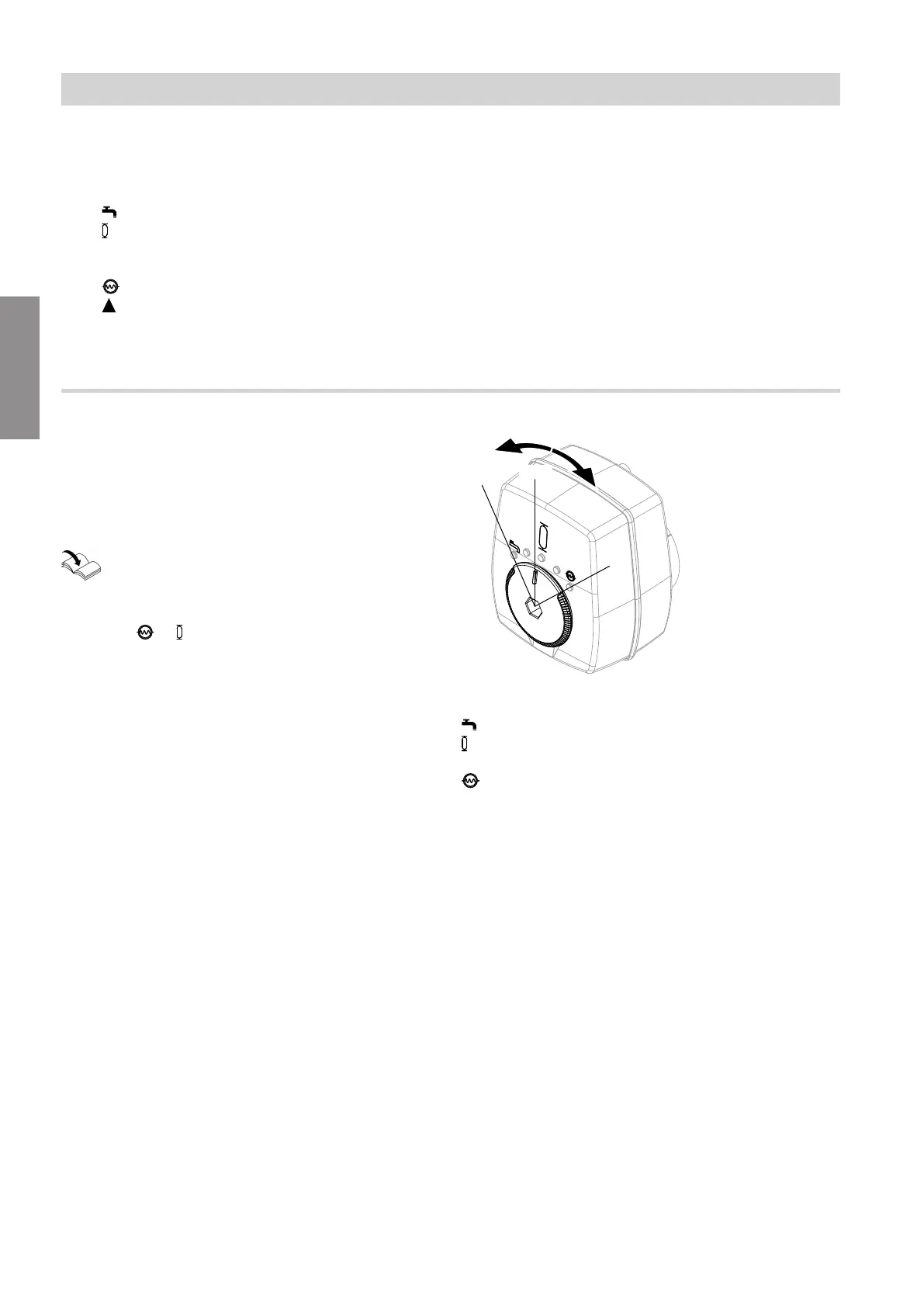
4/3-way valve
The position of the 4/3-way valve determines which
system components receive a flow of heating water.
The 4/3-way valve is actuated via a 0 to 10 V signal.
The current position of the 4/3-way valve in % can be
called up in the menu "Information" > "General".
Operating instructions for the heat pump
For flow rate control, the 4/3-way valve moves to a
position of
—
= 0 % to 50 % as required.
Fig. 14
≙ 100 %: Only DHW heating
≙ 50 %: Only integral buffer cylinder or heating/
cooling circuit 2
≙ 0 %: Only heating/cooling circuit 1
Function description
Flow rate control with Hydro AutoControl (cont.)
6218234
Functions