35
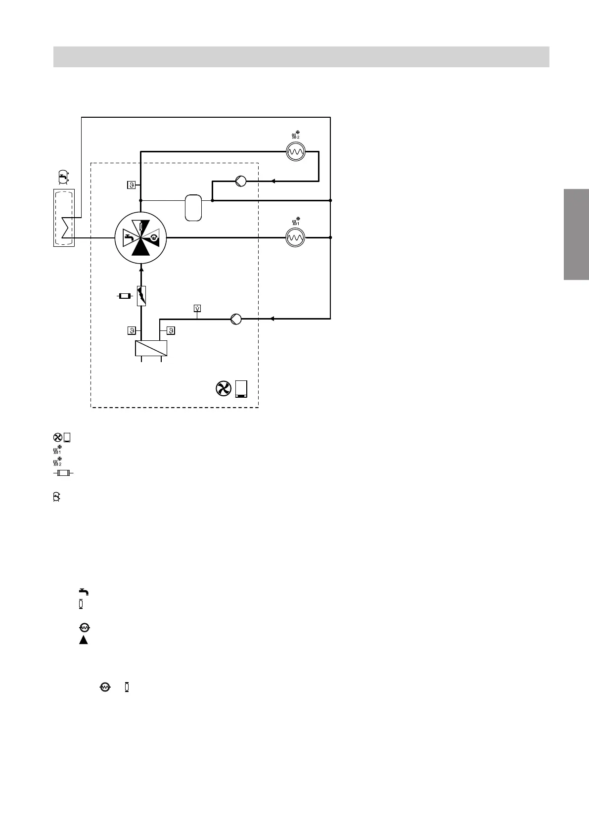
Flow diagram for indoor units with 2 integral heating/cooling circuits: Mixed mode for heating/cooling cir-
cuit 1 and heating/cooling circuit 2
Fig. 8
Air source heat pump
Heating/cooling circuit 1
Heating/cooling circuit 2
Instantaneous heating water heater
(not available with all heat pump types)
DHW cylinder
(integrated in floorstanding indoor units)
A
Return temperature sensor, secondary circuit
B
Condenser
C
Flow temperature sensor, secondary circuit
D
4/3-way valve
Positions:
DHW heating
Integral buffer cylinder or heating/cooling cir-
cuit 2
Heating/cooling circuit 1
Open flow direction
E
Flow temperature sensor, heating/cooling cir-
cuit 2
F
Heating circuit pump, heating/cooling circuit 2
G
Integral buffer cylinder
H
Heating circuit pump, heating/cooling circuit 1
K
Flow sensor
■
A voltage of 0.5 V to 7.9 V is applied to the 4/3-way
valve:
Position — = ≥ 5 % to < 50 %
■
The flow temperature for heating/cooling circuit 1 is
controlled by modulating the compressor.
The flow temperature for heating/cooling circuit 2 is
controlled via the mixing function of the 4/3-way
valve and the speed of the integral heating circuit
pump.
■
The heating circuit pumps for heating/cooling cir-
cuit 1 and heating/cooling circuit 2 are switched on.
Note
If the minimum flow rate is not reached, water flows
through the integral buffer cylinder.
Function description
Heating/cooling (cont.)
6218234
Functions