Document: LT0439 Vigilant MX1-Au Operator Manual
Issue 1.73 23 October 2018 Page 11-17
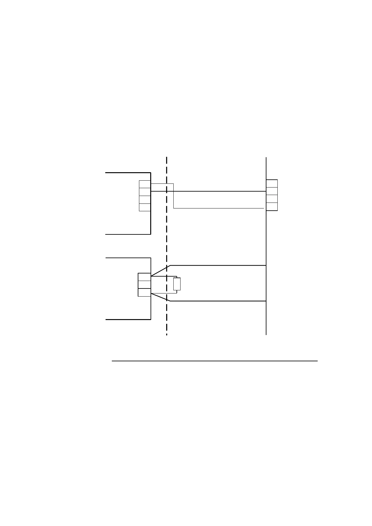
The RZDU method will be described as it is the usual interface (refer
Figure 11-13). The other methods can be arranged by using clean-
contact relay outputs from MX1 (for example, Anc 1 or 2, or relays
controlled by GP Out 1 and 2 or even the 16 open-collector outputs on
the LCD keyboard). Supervision of the QE90 for faults can use a GP
Input as shown in Figure 11-13.
Wiring
Using the RZDU output is allowed only when the QE90 and MX1 are co-
located, since a single fault on the RZDU wiring will stop all zone alarm
signals from working.
PA0481
Interface
In QE90
0 V
+V
TX
RX
NC
NO
C
ELD
0V
RX
TX
QE90
GP INPUT
1 of 2
0V
MX 1
CONTROLLER
EWIS Fault
Relay
RZDU
Figure 11-13 -
MX1
to QE90 Wiring Using RZDU and EWIS Fault Relay
The GP Input ELD can have any value between 1.5k and 3.3k. 2.7k
ELDs are supplied with MX1.
Refer to the QE90 Installation Manual (LT0088) Chapter 22.2 for details
of how to provide the RZDU input in QE90 using the PA0481 Interface
Module. The MX1’s RZDU TX and 0V outputs are wired to the RX and
0V inputs respectively on the PA0481.
The QE90’s general fault relay (normally energised) C and NC terminals
can be wired to one of the MX1’s GP inputs for fault supervision as
shown in Figure 11-13.