Chapter 1: Memory Array Hardware Installation
18
Violin 6000 Series Memory Array Installation Guide
535-0045-00 Rev 02
Installing the Cage Nuts
Cage nuts and screws are included in the accessory kit to secure the Memory Array to the top hole
on the rack ears and the equipment rack. Use either the supplied cage nuts or the screws,
depending on the style of your equipment rack.
Note: If the equipment rack in which the Memory Array will be installed is a square-hole rack, it
is recommended that you install the cage nuts before mounting the Memory Array.
Use the cage nuts for square-holed equipment racks. If the equipment rack has threaded holes, you
can secure the Memory Array to the equipment rack after the Memory Array is installed.
To install the cage nuts:
1. Identify the location in the equipment rack where the cage nut will reside. The cage nut will
align with the top hole on the rack ear, which is two holes above the top clip on the slide rail.
2. Remove the screw from the cage nut and set it aside for later use.
3. Insert the cage nut into the equipment rack at the identified location.
4. Using a flat-blade screwdriver, from the inside of the equipment rack, compress the cage nut
clip until the cage nut locks into place.
5. Repeat step 4 using another cage nut on the other side of the equipment rack.
Attaching the Rack Ears (Optional)
Note: Optional rack ears are included in the Memory Array shipping box if you do not want to
secure the Memory Array chassis to the equipment rack using the front bezel. Securing the Memory
Array to the equipment rack is covered on page 29.
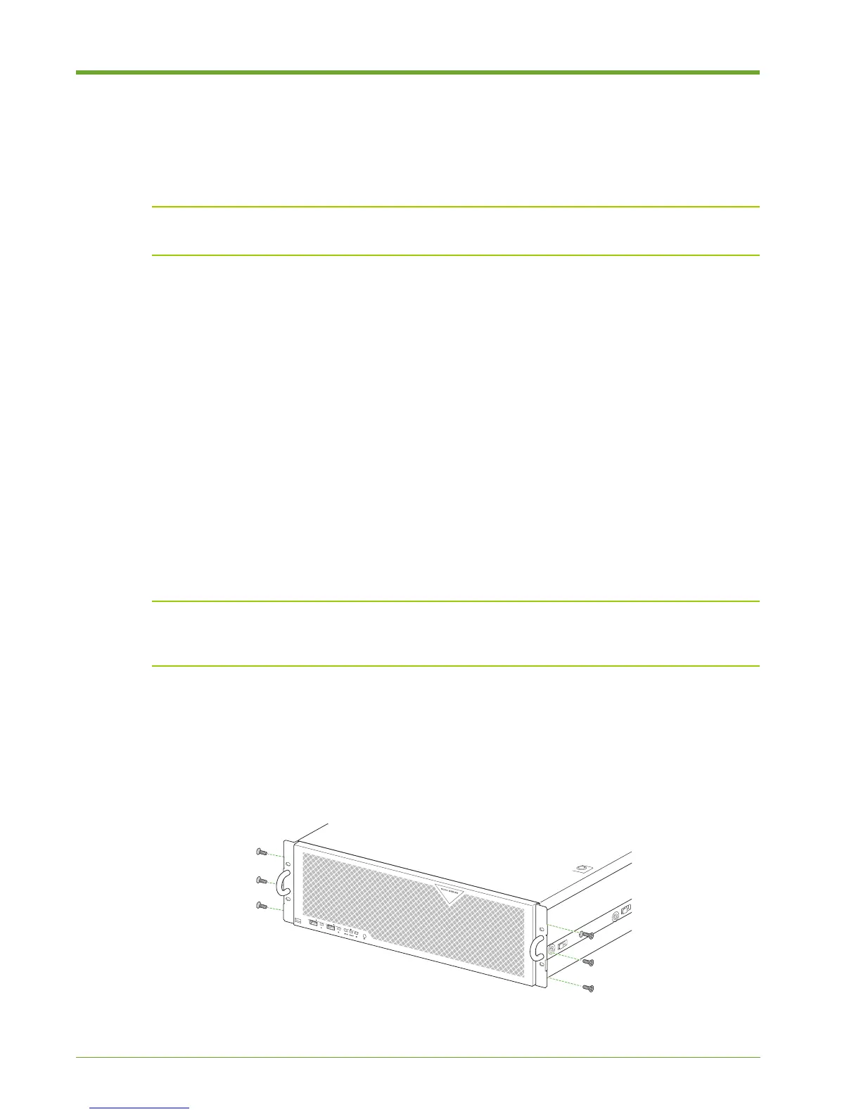
Attach the rack ears to the two front corners of the Memory Array chassis to assist with sliding the
system in an out of the equipment rack.
1. Remove the rack ears and six flathead screws from the accessory kit.
Figure 1.11 Attaching the Left Cable Management Bracket and Routing the Cables