Connecting the Memory Array to a Host or Network
535-0045-00 Rev 02
Violin 6000 Series Memory Array Installation Guide
23
See the Violin 6000 Series Memory Array User’s Guide for information about rebooting and shutting
down the Memory Array and the internal modules.
Connecting the Memory Array to a Host or Network
This section describes the steps required to connect the various types of interface cables from the
Memory Array to a host or storage area network (SAN). See Standard System Configurations on
page 9 for general guidelines for all supported configurations.
Connecting PCIe Cables to the Memory Array
This section describes the steps required to connect a single Memory Array to a single host. Several
different direct-attached storage configurations are possible depending on the number of hosts and
whether those hosts require shared access to the volumes or LUNs within the Memory Array. See
Direct-attached Storage Configurations on page 11 for information on other direct-attached
configurations.
The Memory Array communicates with the direct-attached host computer using a PCI Express
(PCIe) connection. There are two Array Controllers Modules (ACMs) in the system. Each Array
Controller provides two PCIe x8 Gen2 ports, making four PCIe ports available to two hosts. Only
two external hosts are supported. Two PCIe cables must be used when connecting the Memory
Array to an external host.
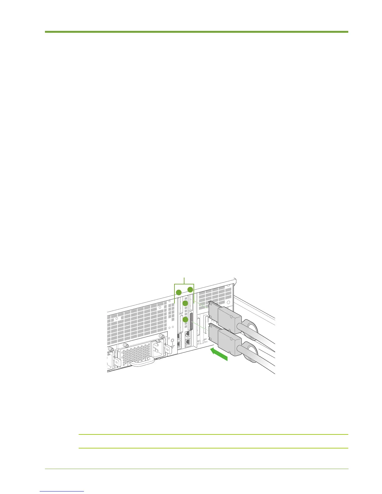
To connect the PCIe cables to the Memory Array:
1. Align the connectors of the PCIe cables with the appropriate PCIe connectors at the rear of the
Memory Array chassis. Note the arrangement of the ACMs: ACM A is on the right and ACM B
is on the left. PCIe port 1 is on the top and port 2 is on the bottom.
2. Securely plug the PCIe cables into the PCIe connectors of the appropriate PCIe ports.
Note: Ensure that the bend radius of the PCIe cable is greater than 1.9".
Figure 1.16 Connecting the PCIe Cables to the Memory Array