Vishay Micro-Measurements System 7000 Programmer’s Reference Manual
Page 32 of 142
Examples of Limits-based Recording
Example 1 – Normal
Limits
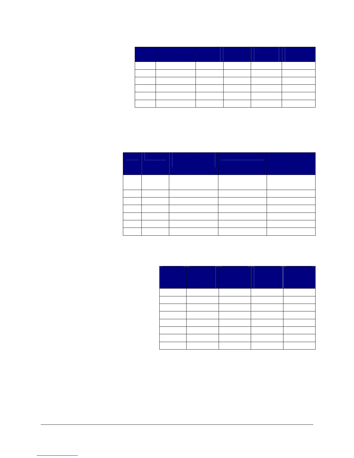
Table 8 represents a limit
conditions table with 3 limits
defined.
We have 3 cards in our
system, each has a limits type
of normal. Remember when
the limit type is normal each channel
can only have 1 limit assigned.
On card 1, we assign limit condition 0 to channel 2. Also on card 1, we assign limit condition 1 to
channel 3. On card 2,
we assign limit condition
0 to channel 4. On card
3, we assign limit
condition 2 to channel 5.
All of the other channels
have the number of limit
conditions set to 0.
We also define the
recording type for the
card. Global limits are
not active.
Table 10 shows the readings that
satisfy the limit conditions for each
channel in red.
Table 11 shows the recorded scans for each card. Green represents out of limit values. Orange and
green represents readings that are recorded.
Recorded Scans for Card 1:
Scan 2 is recorded because channel 3 has tripped the limit of “less than 50”. Scan 4 is recorded
because channel 2 trips the limit of “greater than 1000”. Since the recording type is “record while
limit active” scans are recorded through scan 6.
Index
Condition Lower
Limit
Upper
Limit
Pre-Limit
Scans
Post-Limit
Scans
0 Greater Than
not used
1000 0 0
1 Less Than 50 not used
0 0
2 Outside 700 800 0 0
:
None not used
not used
0 0
:
None not used
not used
0 0
49 None not used
not used
0 0
Table 8
Card
Channel
Limit Condition
Assignment
Recording type Number of
Limit
Conditions
1 Record while
limit active
2 0 1
3 1 1
2 Continuous
4 0 1
3 SingleShot
5 2 1
Table 9
Scan
Number
Card 1
Channel 2
Reading
Card 1
Channel 3
Reading
Card 2
Channel 4
Reading
Card 3
Channel 5
Reading
1 400 100 400
400
2 500
45
500
500
3 800 55 800 800
4
1050
55
1090 1050
5
2000
60
2200 2000
6
3000
50 990 750
7 900 70 900
900
8 600 100 600
950
Table 10