27
1
(2)
(4)
(2)
(1)
(3)
(4)
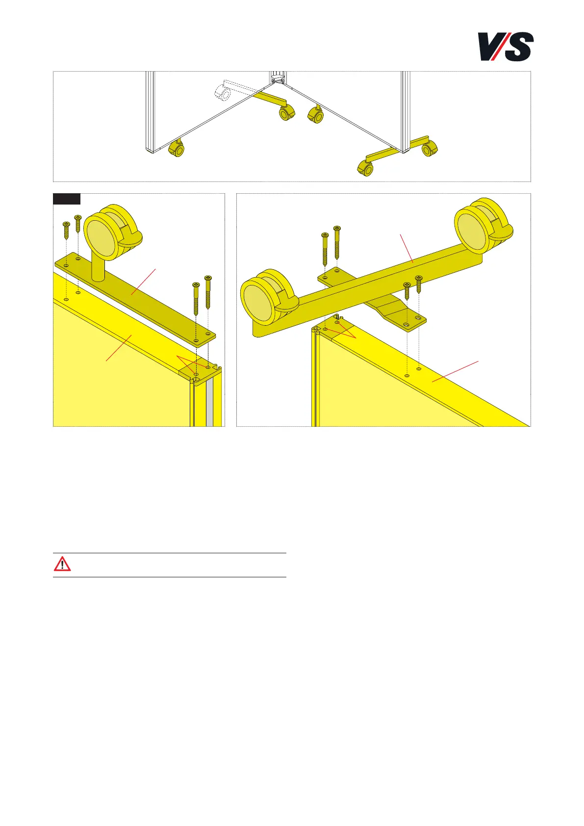
Align the castor connector parallel with cover profile (4).
Secure the castor connector in the aluminium profile and
screw down with 2 4.8 x 19 mm pan-head tapping screws.
Mounting stabilisers (part no. 97-945): Screw stabiliser (1)
into screw channel (2) of the clamping rail with 2 4.8 x
60 mm pan-head tapping screws. Align the stabiliser parallel
with cover profile (4). Secure the stabiliser in the aluminium
profile and screw down with 2 4.8 x 19 mm pan-head
tapping screws.
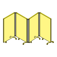
7. Paravent. Stabilisers and castors.
Mounting stabilisers and castors: Mount the stabilisers (1)
and castors with the screen surface lying down. Lay down
on the work surface to avoid damaging a ceiling or similar.
Mounting castor connector (part no. 97-951): Screw castor
connector (3) into screw channel (2) of the clamping rail
with 2 4.8 x 60 mm pan-head tapping screws.
Caution! Pay attention to the position of the castor.
It must be pointing inwards, see Fig. 1.