30
(11) (12)
(11)
(12)
(13)
(13)
(10)
(14)
(7)
(2)
(1)
(3)
(4)
(4)
(6)
(6)
(5)
(8)
(7)
(1)
(3)
(1)(2)(2)(1)
Reattach caps (3) on the frame profiles. Screw on upper end
plate (6) of connection profile (4) again. When correctly
assembled, the attachment element can be turned in any
direction without collisions.
Connecting further attachment elements, see Paravent,
Page 29.
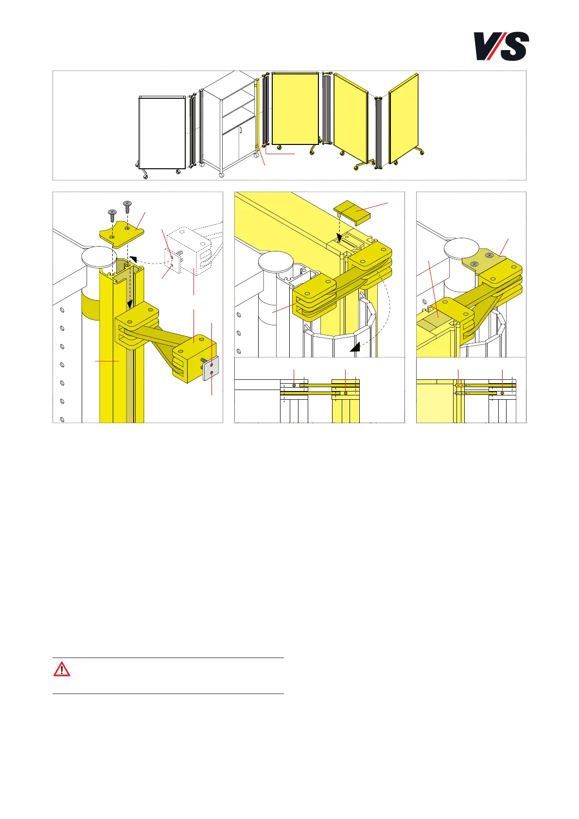
10. System connection Serie 600.
Connecting attachment element to Serie 600. Models
05515-05528.
Remove caps (3) on the frame profiles. Unscrew upper end
plate (6) from connection profile (4). Erect attachment ele-
ment (1) and Serie 600 module (2) approx. 100 mm apart.
Feed the first hinge (5) completely into the two end grooves
in the frame profiles or connection profile and slide
downwards. Likewise feed connection profile (7) into the
grooves. To mount the top hinge (8), position the screen pa-
rallel with the cupboard.
Feed the second hinge (8) completely into the end grooves in
the frame profile. Align all the components and fully tighten
hinge screws <(10) and (11) (M4 x 12 3 WAF). Access the
remaining screws <(13) and (12)> by moving the screen
through 270° (9).
Caution! Make sure without fail that the hinges and
connection profile (7) are correctly located in the
frame-profile or connection-profile grooves.