31
(2)
(1)
(5)
(8)
(7)
(3)
(4)
Serie 901
Serie 901
(13)
(11)
(12)
(10)
(9)
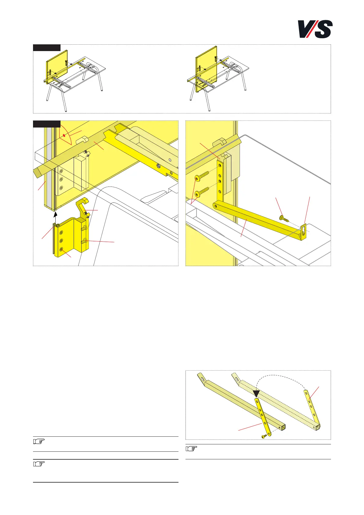
11. System connection Serie 901.
Connecting screens/adaptable screen to Serie 901.
Screen Models 05900-05908, adaptable screen models
05910-05923.
Slide the table connection with clamping block (1) on both
sides into the function groove in frame profile <h>. Position
at the desired height. Tighten the 3 M5 x 12 mm screws (2)
on both sides in the clamping block. Engage the panel in
cross-tube (3). Position in a line and tighten with threaded
pin (4) (M5 x 16 mm) on both sides.
Alignment: The panel can be aligned horizontally to the ta-
ble top by gently releasing screws (2) in the clamping block.
The panel can be aligned at right angles to table top (7) by
releasing screws (5) (M8 x 16 mm).
Fine adjustment of the adaptable screen is performed by
means of the adjustable feet on the floor. The adjustable glide
elements can be turned by hand by gently raising the adap-
table screen. Approx. 10 mm height travel.
Important! Serie 901 sit-stand workstations exclusive-
ly with screens is permitted.
Important! The maximum load is:
Screens 20 kg
Adapatable screen 30 kg
Supporting piece of adaptable screen and counter system.
The support piece is prepared as standard for use at the
right-hand corner of the table. Use two M8x20 mm pan-
head tapping screws (10) to connect the supporting piece
(9) to the clamping profile (11). Adjust the lug (12) on the
supporting piece and fix to the crosspiece using two
M4.2x16 mm self-tapping screws (13).
The supporting piece can only be fixed directly to the cros-
spiece. As a result, it must be moved over from the right to
the left-hand side if required. To do this, it is necessary to
swap over the mounting (14).
Important! Make sure that the adaptable screen and
counter system are vertically aligned
(14)
(14)