6-4 BA 5001-6001 US – Edition 1.2 * * 6001b610.fm
Specifications
6.9 Electric system 5001
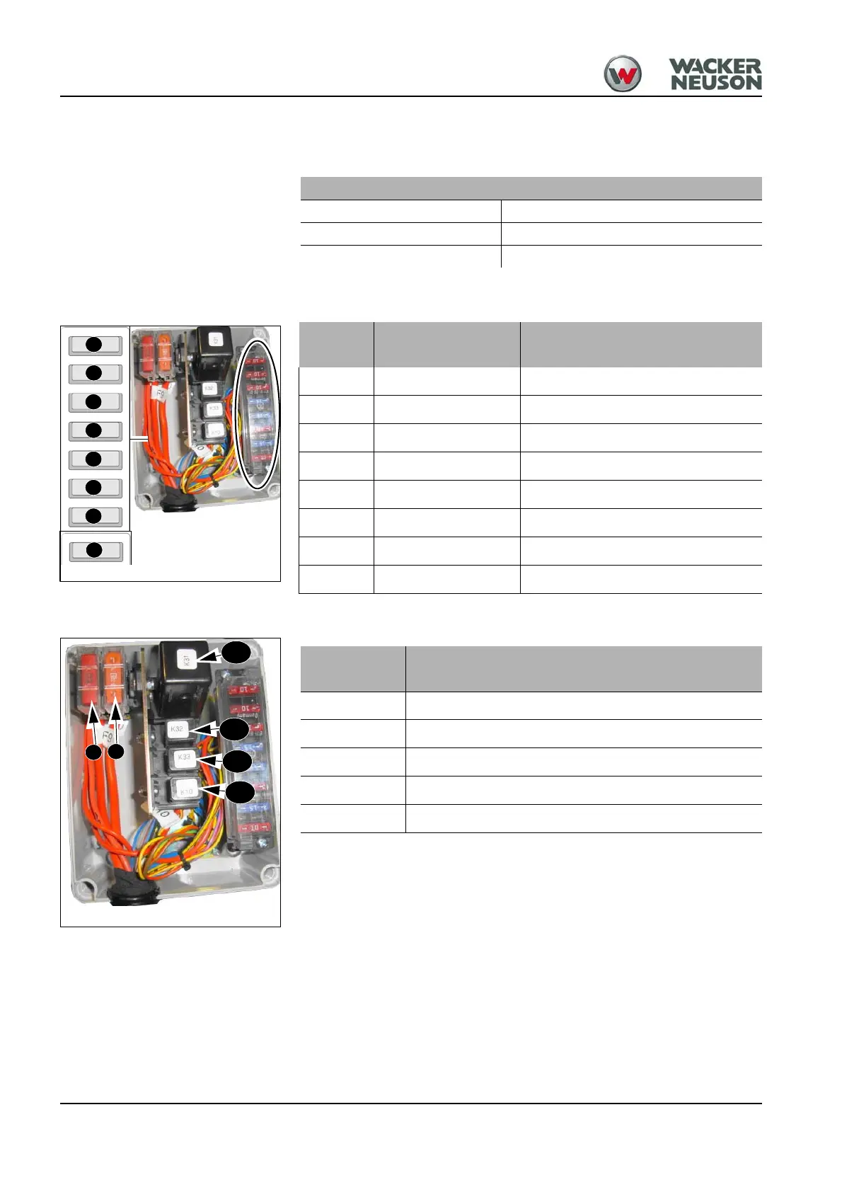
Fuse box
Relays
The relays are located in the relay box under the the floor panel of the control stand
Electric system
Alternator 12 V 55 A
Starter 12 V 2.6 kW
Battery 12 V 88 Ah
F1
F2
F3
F4
F5
F6
F7
Fig. 92: Fuse box
F8
Fuse
Rated
current (A)
Protected circuit
F 1 10 A – Instrument panel, fuel supply
F 2 10 A – Drive solenoid valves
F 3 10 A – Horn, brake lights
F 4 15 A – Turn indicators
F 5 15 A – High beam
F 6 10 A – Low beam
F 7 15A – Clearance light
F8 10 A – Hazard warning system
K 31
K 33
K 32
Fig. 93: Relays
F10
F9
K 10
Switching relay
no.
Protected circuit
F 9, F10 – Main fuses (50 A)
K 31 – Turn indicator relay
K 32 – High beam relay
K 33 – Low beam relay
K 31 – Start relay
 Loading...