Installing the 1525 Pump 44
2
Attaching the Compression Fittings to the Tubing
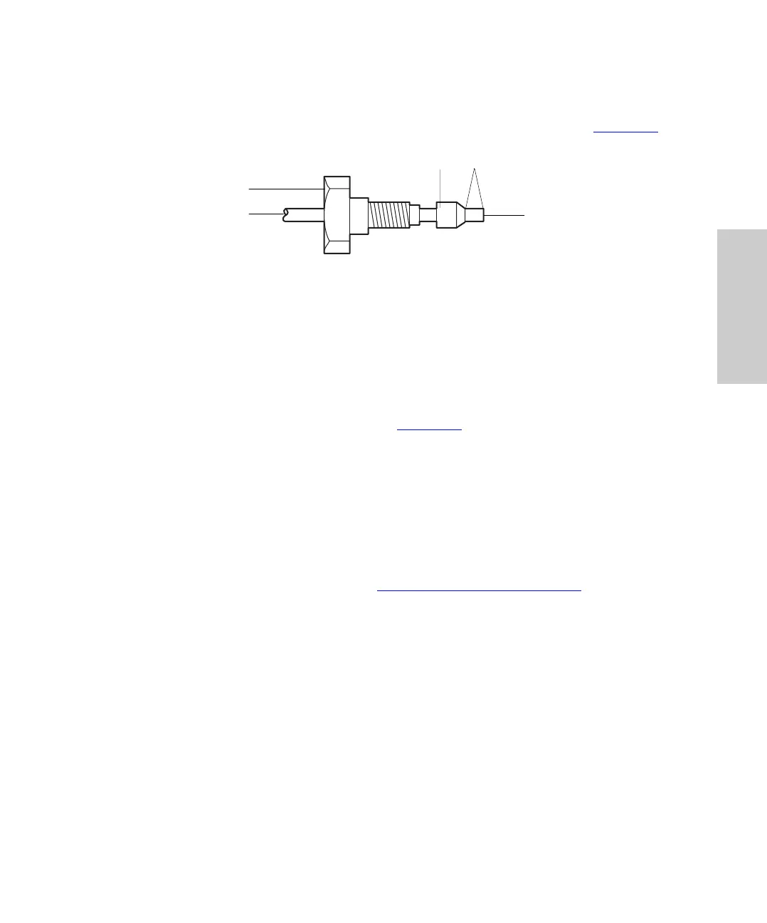
1. Slide a compression screw onto one end of the tubing, then slide a ferrule onto the
tubing with the large end of the taper toward the screw, as shown in Figure 2-5
.
Figure 2-5 Standard Ferrule and Compression Screw Assembly
2. While firmly pressing the tubing into the pump outlet or other system component,
finger-tighten the compression screw.
3. Use the 5/16-inch wrench to tighten the screw another quarter turn. This seats the
ferrule against the tubing.
4. Unscrew the assembled fitting and verify that the length of tubing extending beyond
the ferrule is 0.12 inch (3 mm). (See Figure 2-5
.)
5. Repeat steps 1 to 4 for the other end of the stainless steel tubing.
Making the Connections
1. While pressing one end of the tubing assembly into the pump outlet fitting,
finger-tighten the compression screw, then use the 5/16-inch wrench to tighten the
screw another 1/8-turn.
Note:
Leave the instrument end of the outlet tubing disconnected until you have
primed the pump as described in Section 3.2.1,
Priming the Pump.
2. After you primed the pump, press the free end of the tubing assembly into the
injector or next device in your HPLC system and finger-tighten the compression
screw. Then use the 5/16-inch wrench to tighten the screw another 1/8-turn.
2.4.6 Connecting Fluid Waste Lines
Follow the instructions in this section to connect the fluid waste lines. The instructions
describe how to do the following:
• Connect the reference valve and optional manual injector waste lines
• Connect the drip tray waste line
Compression Screw
Ferrule
Smooth, Square End
Tub ing
0.12 Inch