Making Fluidic Connections 39
2
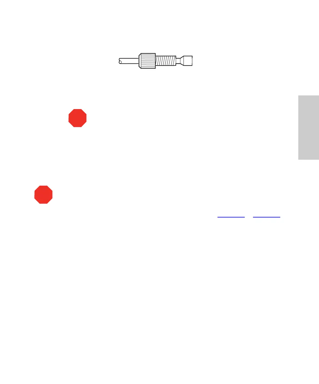
Figure 2-3 Reverse Ferrule and Compression Screw Assembly
5. Firmly seat the tubing end into the inlet manifold on the pump, then finger-tighten the
compression screw.
6. Repeat steps 1 to 5 for the second pump.
Connecting Eluent Tubing to an Eluent Reservoir
1. Slide an inlet tubing label onto the appropriate tube (see Figure 1-3 or Figure 1-4).
2. Insert the free end of the 1/8-inch ETFE inlet tubing into the cap of an eluent
reservoir.
3. Slide one piece of ETFE tubing over the end of the 1/8-inch ETFE tubing for about
0.75 in. (1.9 cm).
4. Insert the stainless steel tubing fitting on the solvent filter into the open end of this
tubing.
5. Install the cap onto the eluent reservoir and push the tubing through the cap until the
filter reaches the bottom of the reservoir.
6. Repeat steps 1 through 5 for the second pump.
2.4.2 Installing Different Mixer Configurations
The Waters 1525µ and 1525EF HPLC Pumps can be used with various configurations of
gradient mixers. This section describes these configurations and how to install each one.
STO
Attention:
To avoid damaging the ferrule, do not overtighten the
compression screw.
STO
Attention:
To avoid having eluent leak from a pump outlet, position each eluent reservoir
below its corresponding pump inlet until the outlet is connected to the system.
TP01170
Tubing
Compression
Ferrule
Tubing End
(Straight and Smooth)
(Flush with Tubing End)
Screw