Watlow PM LEGACY
™
Limit Controller • 20 • Chapter 2 Install and Wire
Warning:
ç
Use National Electric (NEC) or
other country-specific standard
wiring and safety practices when
wiring and connecting this con-
troller to a power source and to
electrical sensors or peripheral
devices. Failure to do so may
result in damage to equipment
and property, and/or injury or
loss of life.
Note:
Maximum wire size termination
and torque rating:
• 0.0507 to 3.30 mm
2
(30 to 12
AWG) single-wire termination
or two 1.31 mm
2
(16 AWG)
• 0.56 Nm (5.0 in-lb.) torque
Note:
Adjacent terminals may be la-
beled differently, depending on
the model number
.
Note:
To prevent damage to the con-
troller, do not connect wires to
unused terminals.
Note:
Maintain electrical isolation
between analog input 1, digital
input-outputs, switched dc/open
collector outputs and process
outputs to prevent ground loops.
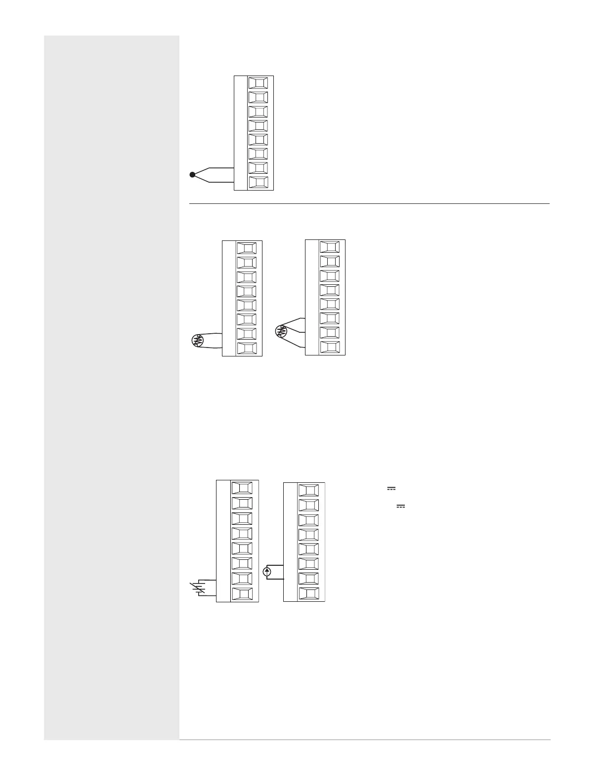
Input 1 Thermocouple PM6[L] _ _ J-_ _ _ _G_ _
-
+
L1
K1
J1
L2
K2
T1
S1
R1
Slot A
• 2kΩ maximum source resistance
• >20MΩ input impedance
• 3µA open-sensor detection
• Thermocouples are polarity sensitive. The negative
lead (usually red) must be connected to S1
• To reduce errors, the extension wire for thermocou-
ples must be of the same alloy as the thermocouple
Input 1 RTD PM6[L] _ _ J-_ _ _ _G_ _
L1
K1
J1
L2
K2
T1
S1
R1
S1
S3
Slot A
L1
K1
J1
L2
K2
T1
S1
R1
S1
S2
S3
• Platinum, 100 and 1kΩ @ 0°C
• Calibration to DIN curve (0.00385
Ω/Ω/°C)
• 20Ω total lead resistance
• RTD excitation current of 0.09mA
typical. Each ohm of lead resistance
may affect the reading by 0.03°C.
• For 3-wire RTDs, the S1 lead (usually
white) must be connected to R1 and/
or R2
• For best accuracy use a 3-wire RTD
to compensate for lead-length resis-
tance. All three lead wires must have
the same resistance
Input 1 Process PM6[L] _ _ J-_ _ _ _G_ _
-
+
L1
K1
J1
L2
K2
T1
S1
R1
Slot A
Volts
-
+
T_
S_
Amperes
Slot A
• 0 to 20mA @ 100Ω input impedance
• 0 to 10V (dc) @ 20kΩ input impedance
• 0 to 50mV (dc) @ 20kΩ input imped-
ance
• Scalable

 Loading...


