3-34 | CFW-11
SRBXX (Safety Stop
board)
XC25
1 (STO1) (24 Vdc) 13
(DGND*) 11
3 (STO2)
2 (GND1)
4 (GND2)
XC1
CC11 (control board)
Figure 3.19 - Internal control connections to disable Safety Stop function
Table 3.8 - Minimum separation distances between wiring
Cable Length
Minimum Separation
Distance
≤ 30 m (100 ft) ≥ 10 cm (3.94 in)
> 30 m (100 ft) ≥ 25 cm (3.94 in)
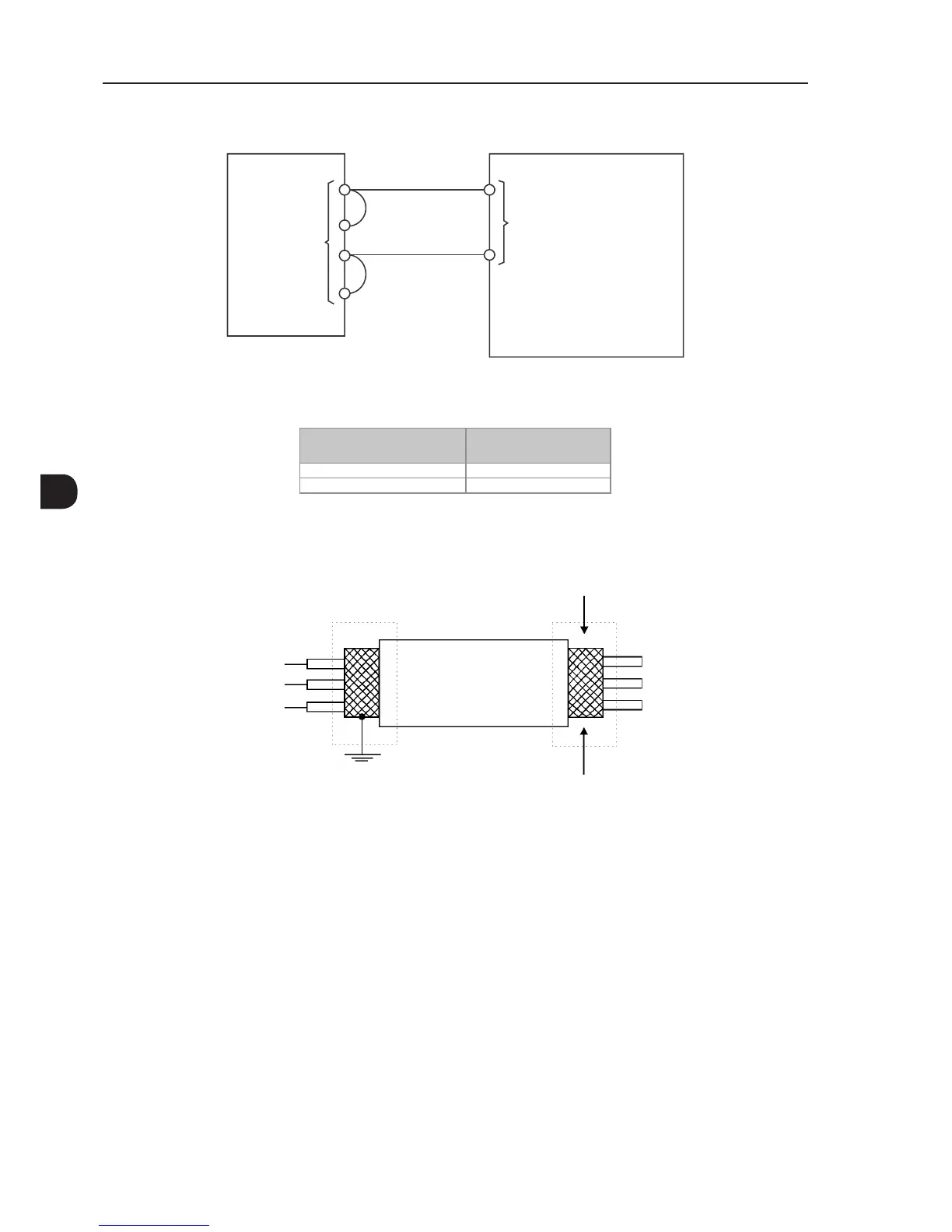
4. The correct connection of the cable shield is shown in Figure 3.20 on page 3-34 and Figure 3.21 on page
3-35.
Do not ground
Inverter
side
Insulate with tape
Figure 3.20 - Shield connection