14
APPLICATIONS
Table 14.5: Description of the control setpoint source
P920 Description
0
It defines that the control setpoint source in automatic mode of the PID controller will be the value programmed in parameter P911
via HMI of the frequency inverter or written via communication networks
1
It defines that the control setpoint source in automatic mode of the PID controller will be the value read by the analog input AI1.
The value is converted according to the engineering unit 1 and viewed in parameter P911
2
It defines that the control setpoint source in automatic mode of the PID controller will be the value read by the analog input AI2.
The values is converted according to the engineering unit 1 and viewed in parameter P911
3
It defines that the control setpoint source in automatic mode of the PID controller will be the value defined through the electronic
potentiometer function via the Increase Setpoint (DI3) and Decrease Setpoint (DI4) commands. The value of the count is
stored in parameter P911
4
It defines that there will be two control setpoints in automatic mode of the PID controller selected via logical combination of
digital input DI3. The selected control setpoint value is viewed in parameter P911
5
It defines that there will be three control setpoints in automatic mode of the PID controller selected via logical combination of
digital inputs DI3 and DI4. The selected control setpoint value is viewed in parameter P911
6
It defines that there will be four control setpoints in automatic mode of the PID controller selected via logical combination of
digital inputs DI3 and DI4. The selected control setpoint value is viewed in parameter P911
When the control setpoint is via logical combination of digital inputs DI3 and DI4 (P920 = 4, 5 or 6), the following
truth table must be used so as to obtain the control setpoint of the PID controller in automatic mode.
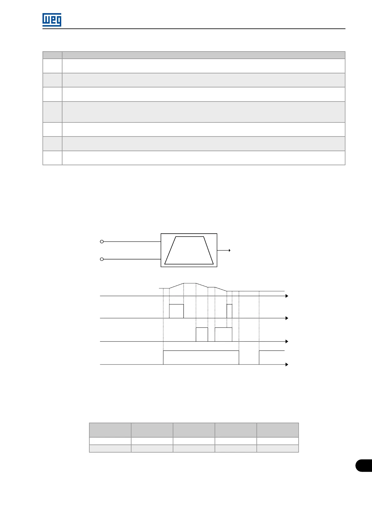
Figure 14.3 on page 14-9 shows the operation of the EP function: when digital input DI3 is activated, the control
setpoint value (P911) is incremented, and when digital input DI4 is activated, the control setpoint value (P911) is
decremented. In case both digital inputs are activated at the same time, the value remains the same.
DI3 - increase SP
DI4 - decrease SP
Ramp for
setpoint
P911 - (control setpoint)
P911 - (control setpoint)
DI3 - increase SP
DI4 - decrease SP
Motor running (RUN)
Active
Inactive
Active
Inactive
Time
Time
Time
Time
Sleep
(A750)
Figure 14.3: PID controller block diagram
When the control setpoint is via logical combination of digital inputs DI3 and DI4 (P920 = 4, 5 or 6), the following
truth table must be used so as to obtain the control setpoint of the PID controller in automatic mode.
Table 14.6: Truth table for the control setpoint via logical combination of digital inputs DI3 and DI4
P912 – Control
Setpoint 1
P913 – Control
Setpoint 2
P914 – Control
Setpoint 3
P915 – Control
Setpoint 4
Digital input DI3 0 1 0 1
Digital input DI4 0 0 1 1
Micro Mini Drives | 14-9