7
COMMAND AND REFERENCES
In general, the digital references defined by parameters such as: HMI keys (P121), Multispeed (P124 to P131) and
E.P. have a scale from 0.0 to 400.0 Hz with resolution of 0.1 Hz.
In digital inputs (DIx), on the other hand, the reference is defined according to the function predefined for P263 to
P266.
The frequency reference applied to the inverter output via frequency input follows the behavior of the parameters
related to it (P230 to P250).
The full scale of the reference is always by P134, that is, maximum value in AIx is equivalent to the frequency
reference equal to P134.
The digital references Serial/USB, CANopen/DeviceNet, Profibus DP, Ethernet and SoftPLC act on a standardized
scale called ”13-bit speed”, where the value 8192 (2
13
) is equivalent to the motor rated frequency (P403). Those
references are accessed by parameters P683 and P685.
The digital references, though, have a different scale and the frequency reference parameters with their range from
0.0 to 400.0 Hz, according to previous descriptions, the frequency value on the ramp input (P001) is always limited
by P133 and P134.
For example, the JOG reference is given by P122, this parameter may be set in up to 400.0 Hz, but the value
applied to the ramp input as reference will be limited by P134 when the function is executed.
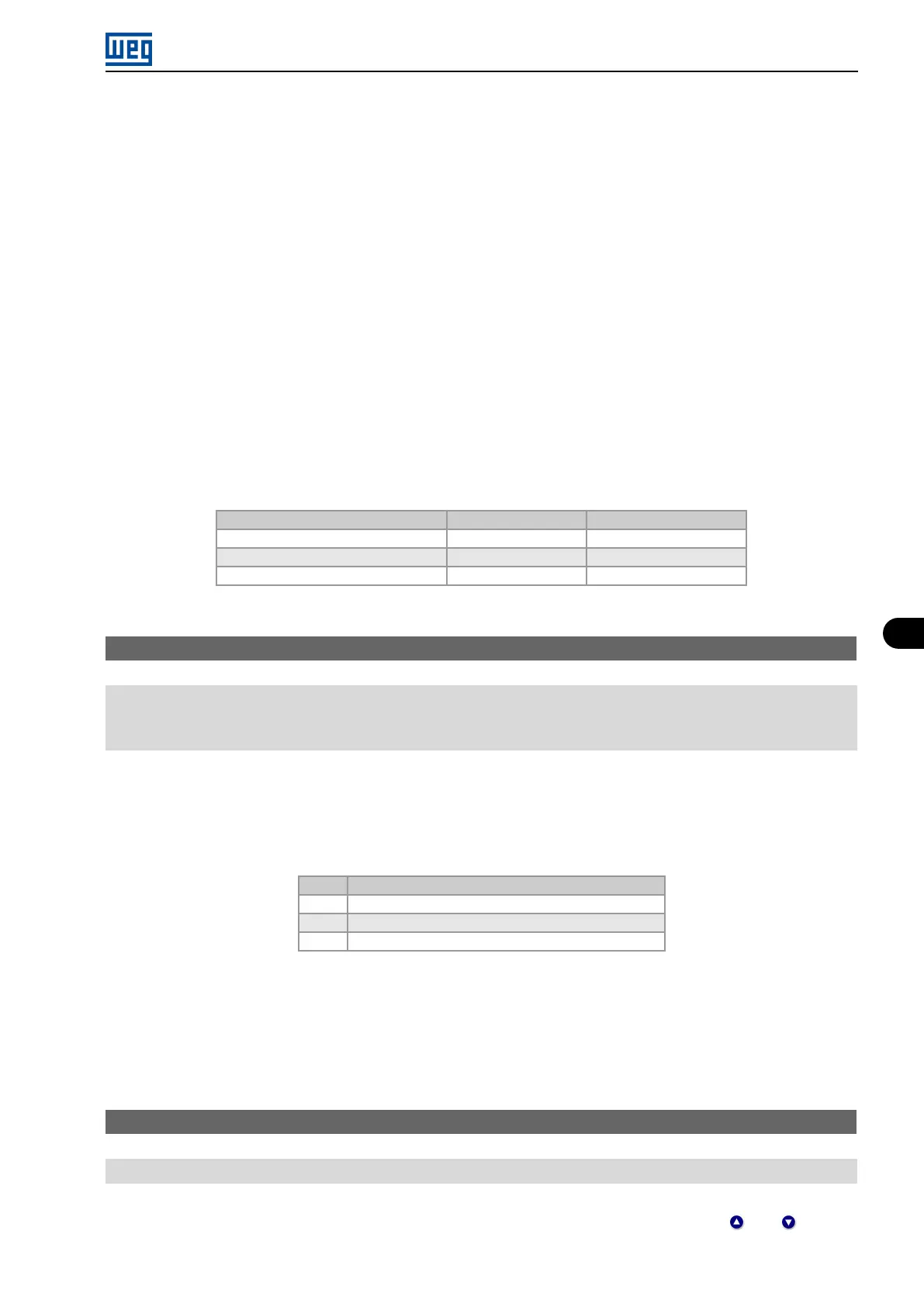
Table 7.2: Summary of the scales and resolutions of the frequency references
Reference Full Scale Resolution
Analog input (AIx) -P134 to P134 10 bits or (P134/1024)
Communication Networks and SoftPLC -400.0 Hz to 400.0 Hz 13-Bit Speed (P403/8192)
HMI Parameter -400.0 Hz to 400.0 Hz 0.1 Hz
P120 - Speed Ref. Backup
Range: 0 = Inactive
1 = Active
2 = Backup by P121
Description:
This parameter defines the operation of the backup function of the speed reference from one of the options Inactive
(P120 = 0), Active (P120 = 1) and by P121 (P120 = 2). This function, in turn, determines the form of backup of the
digital references of the sources: HMI (P121), E.P. and Serial (P683), according to Table 7.3 on page 7-7.
Table 7.3: Options of parameter P120
P120 Reference Initial Values at the Enabling or Power-Up
0 Value of P133
1 Last adjusted value
2 Value of P121
If P120 = Inactive, the inverter will not save the speed reference value when it is disabled. Thus, when the inverter
is enabled again, the speed reference value will become the frequency minimum limit value (P133).
If P120 = Active, the value set in the reference is not lost when the inverter is disabled or powered down.
If P120 = Backup by P121, the reference initial value is fixed by P121 at the enabling or power-up of the inverter.
P121 - Reference via HMI
Range: 0.0 to 400.0 Hz
Description:
Parameter P121 stores the frequency reference via HMI (P221 = 0 or P222 = 0). When the and keys are
active and the HMI in the monitoring mode, the value of P121 is increased and shown on the HMI main display.
Micro Mini Drives | 7-7